
Page 197 - Academic Press Encyclopedia of Physical Science and Technology 3rd BioTechnology
P. 197
P1: GTV/MBR P2: GSS Final Pages
Encyclopedia of Physical Science and Technology EN011L-523 August 10, 2001 11:17
Optical Fiber Techniques for Medical Applications 317
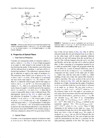
FIGURE 2 Trajectory of a ray in a cylindrical rod. (a) A rod of
FIGURE 1 Reflection and refraction at the interface between two refractive index n 1 in air (n 0 = 1). (b) A rod whose core has a
media of refractive indices n 1 and n 2 (n 1 > n 2 ). (a) Incident angle refractive index n 1 and cladding index n 2 (n 2 < n 1 ).
θ 1 <θ c . (b) Incident angle θ 1 = θ c . (c) Incident angle θ 1 >θ c ; total
internal reflection.
face of the rod are shown in Fig. 2(a). Ray II will be
A. Properties of Optical Fibers refracted inside the rod and refracted back in air. Ray I,
on the other hand, will be totally internally reflected
1. Total lnternal Reflection inside the rod and will emerge from the second face of
the rod. This will also happen when the rod is very thin
Consider two transparent media of refractive indices n 1
and flexible, and in this case the rod is called an optical
and n 2 , where n 1 > n 2 (Fig. 1). A ray of light propagates
fiber. A fiber consisting of a transparent material in air
at an angle θ 1 with respect to the normal to the inter-
is called an unclad fiber. Light will propagate inside the
face between the media. At the interface, part of the beam
rod (or fiber) by a series of internal reflections, even if
will be reflected back to medium 1, and part will be re-
the rod is not in air, as long as n 2 < n 1 . In particular, a
fracted into medium 2. The reflection is specular (the an-
compound rod may consist of the inner part of index
gle of reflection is equal to the angle of incidence θ 1 ).
n 1 , called core, and the outer part of index n 2 , called
The refraction obeys Snell’s law as shown in Fig. 1(a),
cladding. If this rod is thin, the optical fiber formed is
so that n 1 sin θ 1 = n 2 sin θ 2 . If the angle θ 1 is increased,
called a clad fiber. The cross section of the rod (or the
one may reach some angle θ 1 = θ 1c , for which θ 2 = 90 .
◦
fiber) is shown in Fig. 2(b), with the trajectory of an
Here θ 1c is called the critical angle, and for this angle we
incident ray of light. Assume that the angle of incidence
◦
write n 1 sin θ 1c = n 2 sin 90 = n 2 . For every angle of in-
in air is α 0 and that inside the core the beam is refracted
cidence θ 1 >θ 1c , there is no refracted beam. Were there
such a beam, its angle θ 2 would be given by the equation: at an angle α 1 , as shown. We can write n 0 sin α 0 =
1/2
2
n 1 sin α 1 = n 1 cos θ 1 = n 1 (1 − sin θ 1 ) , where n 0 = 1is
sin θ 2 = (n 1 sin θ 1 )/n 2 > (n 1 sin θ 1c )/n 2 = 1. Since this of
the refractive index in air. The angle θ 1 can assume sev
course is impossible, there is only a reflected beam. This
eral values, but its maximum value for total internal reflec-
phenomenon, shown in Fig. 1(c), is called total inter-
tion is the critical value θ 1c , given by n 1 sin θ 1c =−n 2 .We
nal reflection. If medium 1 is glass with n 1 = 1.5 and
medium 2 is air with n 2 = 1, the critical angle is given can calculate α 0max , the value of α 0 corresponding
1/2
2
by sin θ 1c = 1/1.5. In this case, θ 1c = 42 . If medium 2 is to this value of θ: n 0 sin α 0max = n 1 (1 − sin θ 1c ) =
◦
2 1/2
2
soda-lime glass with n 2 = 1.52 and medium 1 is flint glass (n − n ) . This value of n 0 sin α 0max is defined as the
1
2
2
aperture
with n 1 = 1.67, then θ 1c = 65 . It should be mentioned that numerical 1/2 NA: NA = n 0 sin α 0max = (n −
◦
1
2 1/2
in practice the total internal reflection is very efficient. In n ) · (2 ) , where = (n 1 − n 2 )/n 1 . Rays of light
2
impinging on the surface at any angle α 0 <α 0max will
this process more than 0.99999 of the incident energy is
be transmitted through the rod (or the optical fiber). All
reflected, compared to about 0.95 for good metal mirrors.
these rays form a cone of angle α 0max . For angles of
incidence α 0 >α 0max , the ray will be refracted into the
2. Optical Fibers
cladding and then into the air. The cone of light rays that
Consider a rod of transparent material of refractive index could be transmitted by the fiber is a measure for the
n 1 in air (n 0 = 1). Two rays of light incident on one end light-gathering capability of the fiber. The angle of the