
Page 198 - Academic Press Encyclopedia of Physical Science and Technology 3rd BioTechnology
P. 198
P1: GTV/MBR P2: GSS Final Pages
Encyclopedia of Physical Science and Technology EN011L-523 August 10, 2001 11:17
318 Optical Fiber Techniques for Medical Applications
cone α 0max is called the acceptance angle. If n 1 = 1.62 total transmission through real fibers depends on many
and n 2 = 1.52, then NA = 0.56. If the fiber is in air, n 0 = 1 factors, and several of them are listed here:
and α 0max = 34 , but if it is immersed in water, n 0 = 1.3
◦
◦
and then α 0max = 25 . The acceptance angle of the fiber 1. Losses in the coupling of light from a light source
in water is therefore smaller than in air. into the fiber.
In the case of a straight fiber, a ray incident at an angle α 2. Reflection losses at each end of the fiber. This
will be transmitted by the fiber and emerge with the same is called the Fresnel Reflection and is proportional to
2
angle α. For an incident cone of rays, the light emerging [(n 1 − n 0 )/(n 1 + n 0 )] .
from the fiber will also be a cone with the same apex angle. 3. Absorption in the pure material of the core. This
In general, this is also true for a bent fiber. absorption depends on λ.
4. Absorption by impurities.
5. Scattering from the inherent inhomogeneous struc-
3. Transmission in Optical Fibers
ture of the core (Rayleigh scattering); scattering from
A beam of light of intensity I 0 impinges on a transpar- small inhomogeneity of refractive index in the core, and
ent material of thickness L (cm). The beam is trans- in the interface between core and cladding.
mitted through the material and emerges with inten- 6. If the fiber is bent, some of the light leaks out from
sity I. In many cases the ratio between I 0 and I is the cladding.
given by the Beer–Lambert law, I = I 0 exp(−δL), where
−1
δ (cm ) is the absorption coefficient. Physically, af- In order to ensure high transmission through the fiber,
ter traveling L = 1/δ cm, the intensity I 0 is reduced to one has to reduce the losses. In unclad fibers the outer
I 0 /e ≈ I 0 /3, and after traveling L = 2/δ cm it is reduced surface of the fiber is exposed to mechanical or chemical
2
to I 0 / e ≈ I 0 /10. In the engineering literature, the trans- damage, which gives rise to scattering. Therefore the fiber
mission loss A is given in decibels (dB), as defined by has to be a clad fiber. The cladding material should be
A (dB) = 10 log (I 0 /I). As an example, if only 10% of well matched to the core one, and the interface should be
10
the light is transmitted, then I = I 0 /10 and the transmis- of high quality. The core should be very pure, in order to
sion loss is A = 10 log 10 = 10 dB. If the light intensity reduce absorption, be free of defects, and homogeneous,
10
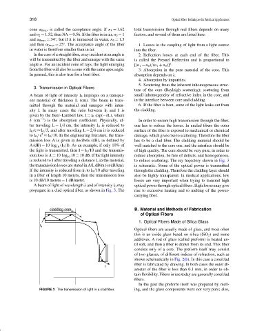
is reduced to I after traveling a distance L in the material, to reduce scattering. The ray trajectory shown in Fig. 3
the transmission losses are stated in A/L dB/m (or dB/km). is schematic. Some of the optical power is transmitted
If the intensity is reduced from I 0 to I 0 /10 after traveling through the cladding. Therefore the cladding layer should
in a fiber of length 10 meters, then the transmission loss also be highly transparent. In medical applications, low
is 10 dB/10 meters = 1 dB/meter. losses are very important when trying to transmit high
A beam of light of wavelength λ and of intensity I 0 may optical power through optical fibers. High losses may give
propagate in a clad optical fiber, as shown in Fig. 3. The rise to excessive heating and to melting of the power-
carrying fiber.
B. Material and Methods of Fabrication
of Optical Fibers
1. Optical Fibers Made of Silica Glass
Optical fibers are usually made of glass, and most often
this is an oxide glass based on silica (SiO 2 ) and some
additives. A rod of glass (called preform) is heated un-
til soft, and then a fiber is drawn from its end. This fiber
consists only of a core. The preform itself may consist
of two glasses, of different indices of refraction, such as
shown schematically in Fig. 2(b). In this case a core/clad
fiber is fabricated by drawing. In both cases the outer di-
ameter of the fiber is less than 0.1 mm, in order to ob-
tain flexibility. Fibers in use today are generally core/clad
fibers.
In the past the preform itself was prepared by melt-
FIGURE 3 The transmission of light in a clad fiber. ing, and the glass components were not very pure; also,