
Page 202 - Academic Press Encyclopedia of Physical Science and Technology 3rd BioTechnology
P. 202
P1: GTV/MBR P2: GSS Final Pages
Encyclopedia of Physical Science and Technology EN011L-523 August 10, 2001 11:17
322 Optical Fiber Techniques for Medical Applications
with little loss and to minimize crosstalk. On the other
hand, in order to get high spatial resolution one has to de-
crease the diameter c of the fiber core to 5–10 µm. In this
case, the ratio between the areas of the cores to that of the
bundle is not high, and the light transmission through the
bundle is reduced. The fibers should therefore have low
loss in order to obtain a good picture.
C. Fabrication of Fiberoptic Bundles
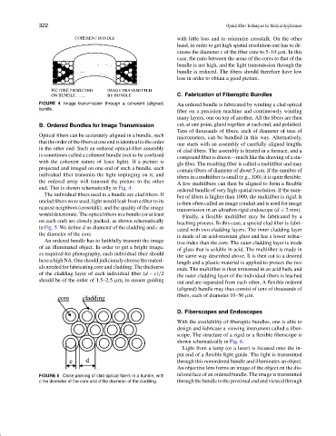
FIGURE 4 Image transmission through a coherent (aligned) An ordered bundle is fabricated by winding a clad optical
bundle.
fiber on a precision machine and continuously winding
many layers, one on top of another. All the fibers are then
B. Ordered Bundles for Image Transmission cut, at one point, glued together at each end, and polished.
Tens of thousands of fibers, each of diameter of tens of
Optical fibers can be accurately aligned in a bundle, such
micrometers, can be bundled in this way. Alternatively,
thattheorderofthefibersatoneendisidenticaltotheorder
one starts with an assembly of carefully aligned lengths
in the other end. Such an ordered optical-fiber assembly
of clad fibers. The assembly is heated in a furnace, and a
is sometimes called a coherent bundle (not to be confused
compound fiber is drawn—much like the drawing of a sin-
with the coherent nature of laser light). If a picture is
gle fiber. The resulting fiber is called a multifiber and may
projected and imaged on one end of such a bundle, each
contain fibers of diameter of about 5 µm. If the number of
individual fiber transmits the light impinging on it, and
fibers in a multifiber is small (e.g., 100), it is quite flexible.
the ordered array will transmit the picture to the other A few multifibers can then be aligned to form a flexible
end. This is shown schematically in Fig. 4. ordered bundle of very high spatial resolution. If the num-
The individual fibers used in a bundle are clad fibers. If
ber of fibers is higher than 1000, the multifiber is rigid. It
unclad fibers were used, light would leak from a fiber to its
is then often called an image conduit and is used for image
nearest neighbors (crosstalk), and the quality of the image
transmission in an ultrathin rigid endoscope (d < 2 mm).
would deteriorate. The optical fibers in a bundle (or at least
Finally, a flexible multifiber may be fabricated by a
on each end) are closely packed, as shown schematically
leaching process. In this case, a special clad fiber is fabri-
in Fig. 5. We define d as diameter of the cladding and c as
cated with two cladding layers. The inner cladding layer
the diameter of the core.
is made of an acid-resistant glass and has a lower refrac-
An ordered bundle has to faithfully transmit the image
tive index than the core. The outer cladding layer is made
of an illuminated object. In order to get a bright image,
of glass that is soluble in acid. The multifiber is made in
as required for photography, each individual fiber should
the same way described above. It is then cut to a desired
have a high NA. One should judiciously choose the materi-
length and a plastic material is applied to protect the two
als needed for fabricating core and cladding. The thickness
ends. The multifiber is then immersed in an acid bath, and
of the cladding layer of each individual fiber (d − c)/2
the outer cladding layer of the individual fibers is leached
should be of the order of 1.5–2.5 µm, to ensure guiding
out and are separated from each other. A flexible ordered
(aligned) bundle may thus consist of tens of thousands of
fibers, each of diameter 10–50 µm.
D. Fiberscopes and Endoscopes
With the availability of fiberoptic bundles, one is able to
design and fabricate a viewing instrument called a fiber-
scope. The structure of a rigid or a flexible fiberscope is
shown schematically in Fig. 6.
Light from a lamp (or a laser) is focused onto the in-
put end of a flexible light guide. The light is transmitted
through this nonordered bundle and illuminates an object.
An objective lens forms an image of the object on the dis-
FIGURE 5 Close packing of clad optical fibers in a bundle, with tal end face of an ordered bundle. The image is transmitted
c the diameter of the core and d the diameter of the cladding. throughthebundletotheproximalendandviewedthrough