
Page 273 - Academic Press Encyclopedia of Physical Science and Technology 3rd BioTechnology
P. 273
P1: GPB/GRB P2: GLQ Final pages
Encyclopedia of Physical Science and Technology EN016J-783 August 1, 2001 10:58
824 Tissue Engineering
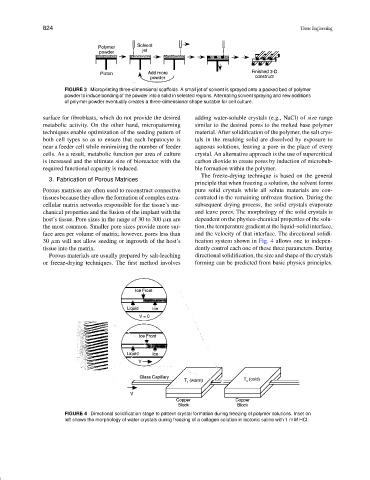
FIGURE 3 Microprinting three-dimensional scaffolds. A small jet of solvent is sprayed onto a packed bed of polymer
powder to induce bonding of the powder into a solid in selected regions. Alternating solvent spraying and new additions
of polymer powder eventually creates a three-dimensional shape suitable for cell culture.
surface for fibroblasts, which do not provide the desired adding water-soluble crystals (e.g., NaCl) of size range
metabolic activity. On the other hand, micropatterning similar to the desired pores to the melted base polymer
techniques enable optimization of the seeding pattern of material. After solidification of the polymer, the salt crys-
both cell types so as to ensure that each hepatocyte is tals in the resulting solid are dissolved by exposure to
near a feeder cell while minimizing the number of feeder aqueous solutions, leaving a pore in the place of every
cells. As a result, metabolic function per area of culture crystal. An alternative approach is the use of supercritical
is increased and the ultimate size of bioreactor with the carbon dioxide to create pores by induction of microbub-
required functional capacity is reduced. ble formation within the polymer.
The freeze-drying technique is based on the general
3. Fabrication of Porous Matrices
principle that when freezing a solution, the solvent forms
Porous matrices are often used to reconstruct connective pure solid crystals while all solute materials are con-
tissues because they allow the formation of complex extra- centrated in the remaining unfrozen fraction. During the
cellular matrix networks responsible for the tissue’s me- subsequent drying process, the solid crystals evaporate
chanical properties and the fusion of the implant with the and leave pores. The morphology of the solid crystals is
host’s tissue. Pore sizes in the range of 30 to 300 µm are dependent on the physico-chemical properties of the solu-
the most common. Smaller pore sizes provide more sur- tion, the temperature gradient at the liquid–solid interface,
face area per volume of matrix; however, pores less than and the velocity of that interface. The directional solidi-
30 µm will not allow seeding or ingrowth of the host’s fication system shown in Fig. 4 allows one to indepen-
tissue into the matrix. dently control each one of these three parameters. During
Porous materials are usually prepared by salt-leaching directional solidification, the size and shape of the crystals
or freeze-drying techniques. The first method involves forming can be predicted from basic physics principles.
FIGURE 4 Directional solidification stage to pattern crystal formation during freezing of polymer solutions. Inset on
left shows the morphology of water crystals during freezing of a collagen solution in isotonic saline with 1 mM HCl.