
Page 92 - Academic Press Encyclopedia of Physical Science and Technology 3rd BioTechnology
P. 92
P1: GNB Final Pages
Encyclopedia of Physical Science and Technology EN005F-954 June 15, 2001 20:48
Fiber-Optic Chemical Sensors 805
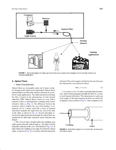
FIGURE 1 Schematic diagram of a fiber-optic chemical sensor system with examples of environmental, clinical, and
industrial applications.
A. Optical Fibers refracted. The critical angle is defined by the ratio between
the clad and the core refractive indices,
1. Basic Characteristics
Optical fibers are waveguides made out of glass or plas- sin ϕ c = n 2 /n 1 . (1)
tic, through which light can be transmitted. Optical fibers
2. Acceptance Cone. In order to get high light transmis-
transmitlightveryefficiently,whichiswhytheyaresouse-
sion, light should propagate through the fiber by a series
ful for many applications. The light transmission through
of total internal reflections. This transmission is achieved
the fiber is based on the phenomenon of total internal
if the angles of the light entering the fiber are within the
reflection (TIR). Optical fibers consist of a core with a
acceptance cone as shown in Fig. 3c. The acceptance cone
refractive index n 1 surrounded by a cladding with a lower
refractive index n 2 (Fig. 2). The difference between the
refractive indices enables the core–clad interface to ef-
fectively act as a mirror such that a series of internal
reflections transmits the light from one end of the fiber
to the other as shown in Fig. 3a. Several principles re-
lated to the light transmission through the optical fiber are
significant for fiber-optic chemical sensor function and
design:
1. The Critical Angle. If light strikes the cladding at an
angle greater than the critical angle ϕ c , the light is totally
internally reflected at the core–clad interface (Fig. 3a). If
light strikes the cladding at an angle less than the critical FIGURE 2 Schematic diagram of an optical fiber showing core
angle, as shown in Fig. 3b, it is partly reflected and partly and clad structure.