
Page 226 - Academic Press Encyclopedia of Physical Science and Technology 3rd Chemical Engineering
P. 226
P1: GJC Final Pages
Encyclopedia of Physical Science and Technology EN004E-182 June 8, 2001 18:16
550 Distillation
TABLE I Typical Steam Pressures Available for bubble-cap trays except when very large flow-rate range-
Distillation abilitiesareneeded.Figure5showsthatliquidflowsacross
Pressure Condensation the tray deck over the outlet weir and passes down the
◦
Designation (bars) temperature ( C) downcomer to the next tray.
Vapor passes through holes in the tray deck where it
Low pressure 2.5 127
comes into contact with the liquid to form a froth, foam,
Medium pressure 15 198
or spray. Columns operating at high pressures typically
High pressure 40 250
must handle large volumetric liquid flow rates per unit
cross-sectional column area. Under such conditions, mul-
75 to 150 mm of insulation to prevent heat gain or loss,
tiple liquid flow passes are used. Figure 6 shows two- and
since distillation fluids are often at temperatures other than
four-pass arrangements. Compared with a single-pass tray
ambient.
(Fig. 5), multipass trays have more downcomer area and
Some distillation columns must handle two or more
a longer total outlet weir length and are capable of han-
feed streams simultaneously. Furthermore, alternative
dling higher liquid rates. However, the number of liquid
feed nozzles are often provided to allow the actual feed-
flow passes is usually minimized since multipass trays
point locations to be altered. By optimizing the feed-point
are prone to liquid and vapor maldistribution and, be-
locations, energy consumption in the reboiler can often be
cause they are structurally more complex, they are more
minimized.
expensive.
The most common energy source used in reboilers is
Recently there has been an increasing trend to replace
steam. Most refineries and petrochemical plants have sev-
the conventional trays depicted in Fig. 5 by trays hav-
eral steam pressure levels available. Some examples are
ing receiving pans that terminate some 15 cm above the
listed in Table I. The condensation temperature of the
tray deck. This provides more column cross-sectional area
◦
steam used in the reboiler must be approximately 15 C
for vapor flow and allows increased vapor capacity. Even
greater than the boiling temperature of the bottom prod-
greater vapor capacity can be obtained from trays that uti-
uct. Other common heat sources used in reboilers are hot
lize localized, upward co-current flow of vapor and liquid.
oil, hot water, and direct firing by burning oil or gas. In
But, as each tray then requires a vapor–liquid separation
contrast, low-temperature columns, in ethylene plants, for
device, they are more expensive and are used only in spe-
example, often use propylene in a refrigeration circuit as
cialized applications.
the heating and cooling medium.
As an alternative to trays, especially at low volumetric
liquid-to-vapor ratios, packing can be used to promote
B. Column Internals
vapor–liquid contact. One approach is to dump specially
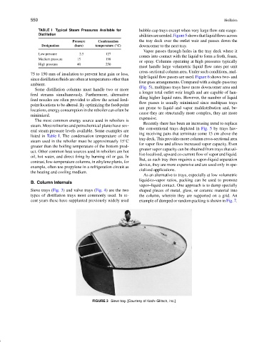
Sieve trays (Fig. 3) and valve trays (Fig. 4) are the two shaped pieces of metal, glass, or ceramic material into
types of distillation trays most commonly used. In re- the column, wherein they are supported on a grid. An
cent years these have supplanted previously widely used example of dumped or random packing is shown in Fig. 7.
FIGURE 3 Sieve tray. [Courtesy of Koch–Glitsch, Inc.]