
Page 418 - Academic Press Encyclopedia of Physical Science and Technology 3rd Chemical Engineering
P. 418
P1: FMX Final Pages
Encyclopedia of Physical Science and Technology EN009J-427 July 6, 2001 20:25
Metalorganic Chemical Vapor Deposition 503
FIGURE 5 Schematic diagram of a typical large-scale horizon-
tal “gas foil” Planetary MOCVD reactor chamber. The precursor
gases are injected in the center of the rotating wafer carrier and
the gas flows horizontally over the individually rotating wafers. FIGURE 6 Photograph of the growth chamber of a large-scale
commercial RDR MOCVD system. The gas injection manifold is
shown in the rear behind the stainless steel growth chamber. The
Commercial state-of-the-art RDR MOCVD reactors large wafer carriers are loaded into the growth chamber through
the rectangular port on the right side of the chamber. The robotic
typically employ stainless-steel growth chambers that are
interface for the robotic computer-controlled platter handling sys-
UHV compatible and are normally fitted with a stainless- tem is shown on the left. (Photograph of EMCORE Model Enter-
steel load-lock chamber through which wafers are loaded prise E450, courtesy of EMCORE Corporation.)
into the growth region using a pneumatically controlled
wafer transfer arm. This greatly reduces the exposure of
Many of the synthetic routes used in the early days of
the growth chamber to ambient O 2 and H 2 O vapor. In the
MOCVD involve reactions with chemicals that can sub-
horizontal MOCVD systems, this is often accomplished
sequently provide impurity atoms in the product. For ex-
by enclosing the reactor chamber entry port in a glove box
ample, the above Reaction (3) can leave the TEGa with
containing a dry N 2 ambient. Advanced MOCVD growth
a small amount of TEAl and Reaction (4) can produce
systems employ full computer control of the flows, pres-
Zn-contaminated TMGa. Note that many metal alkyls are
sures, temperatures, times, and valve sequences associated
with the growth process. New system designs are appear-
ing that are fully compatible with the semiconductor in-
dustry standard robotic interface. The external view of the
growth chamber of a current-generation vertical RDR re-
actor is shown in Fig. 6 and the interior of the growth
chamber of a current-generation horizontal gas-foil rota-
tion Planetary reactor chamber is shown in Fig. 7.
II. PROPERTIES OF COMMON
METALORGANICS AND HYDRIDES
USED FOR MOCVD
The metal alkyls commonly used as precursors for
the MOCVD growth of III–Vs can, in principle, be
made by very simple halogen-containing reagent reac-
tions. A basic example of this process is described by
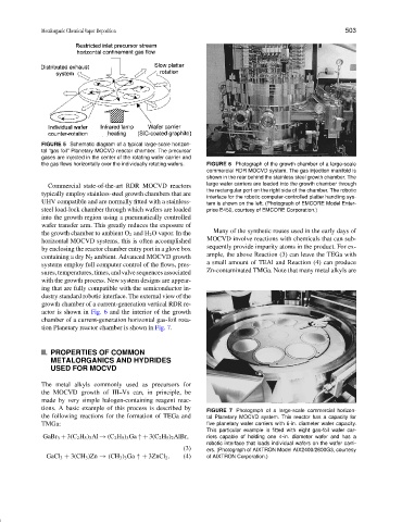
FIGURE 7 Photograph of a large-scale commercial horizon-
the following reactions for the formation of TEGa and tal Planetary MOCVD system. This reactor has a capacity for
TMGa: five planetary wafer carriers with 6-in. diameter wafer capacity.
This particular example is fitted with eight gas-foil wafer car-
GaBr 3 + 3(C 2 H 5 ) 3 Al → (C 2 H 5 ) 3 Ga ↑+ 3(C 2 H 5 ) 2 AlBr, riers capable of holding one 4-in. diameter wafer and has a
robotic interface that loads individual wafers on the wafer carri-
(3) ers. (Photograph of AIXTRON Model AIX2400/2600G3, courtesy
GaCl 3 + 3(CH 3 )Zn → (CH 3 ) 3 Ga ↑+ 3ZnCl 2 . (4) of AIXTRON Corporation.)