
Page 415 - Academic Press Encyclopedia of Physical Science and Technology 3rd Chemical Engineering
P. 415
P1: FMX Final Pages
Encyclopedia of Physical Science and Technology EN009J-427 July 6, 2001 20:25
500 Metalorganic Chemical Vapor Deposition
“injector” or point of origin and the substrate surface with- taxial films. These low-pressure MOCVD systems operate
out interacting with any other molecules (especially im- under controlled pressures using chemical-series vacuum
purities like O 2 or CO 2 ). pump systems (now “dry” oil-free pumps are often used)
to pull the reactants through the chamber at high gas ve-
locities, thus reducing the boundary layer thickness and
3. Precursor Selection
reducing the gas switching time in the chamber. The first
The metalorganic precursor compounds that have been work on low-pressure MOCVD (LP-MOCVD) was re-
most commonly used to grow thin films of semiconduc- ported by J. P. Duchemin et al. (Thompson CSF, France) in
tors and related materials are listed below in Table I, along 1979, who reported the growth of InP using triethylindium
with the currently available vapor pressure data. These (TEIn) and PH 3 , and GaAs using triethylgallium (TEGa)
precursors are typically pyrophoric liquids or high-vapor- and AsH 3 ,at ∼100 Torr (∼13 kPa) in a horizontal re-
pressure solids. The simple metal alkyls (methyl and ethyl actor. This same group also reported the growth of In-
derivatives) are the most often employed for the growth GaAsP alloys lattice-matched to InP at low pressure using
of III–V compound semiconductors since they have rea- TEGa, TEIn, PH 3 , and AsH 3 . Using LP-MOCVD, they
sonably high vapor pressures and can be readily delivered also grew the first InGaAsP/InP injection lasers produced
using a H 2 carrier gas and precursor source temperatures by MOCVD.
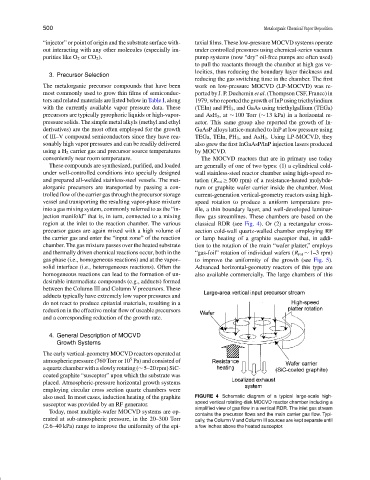
conveniently near room temperature. The MOCVD reactors that are in primary use today
These compounds are synthesized, purified, and loaded are generally of one of two types: (1) a cylindrical cold-
under well-controlled conditions into specially designed wall stainless-steel reactor chamber using high-speed ro-
and prepared all-welded stainless-steel vessels. The met- tation (R rot ≥ 500 rpm) of a resistance-heated molybde-
alorganic precursors are transported by passing a con- num or graphite wafer carrier inside the chamber. Most
trolled flow of the carrier gas through the precursor storage current-generation vertical-geometry reactors using high-
vessel and transporting the resulting vapor-phase mixture speed rotation to produce a uniform temperature pro-
into a gas mixing system, commonly referred to as the “in- file, a thin boundary layer, and well-developed laminar-
jection manifold” that is, in turn, connected to a mixing flow gas streamlines. These chambers are based on the
region at the inlet to the reaction chamber. The various classical RDR (see Fig. 4). Or (2) a rectangular cross-
precursor gases are again mixed with a high volume of section cold-wall quartz-walled chamber employing RF
the carrier gas and enter the “input zone” of the reaction or lamp heating of a graphite susceptor that, in addi-
chamber. The gas mixture passes over the heated substrate tion to the rotation of the main “wafer platter,” employs
and thermally driven chemical reactions occur, both in the “gas-foil” rotation of individual wafers (R rot ∼ 1–3 rpm)
gas phase (i.e., homogeneous reactions) and at the vapor– to improve the uniformity of the growth (see Fig. 5).
solid interface (i.e., heterogeneous reactions). Often the Advanced horizontal-geometry reactors of this type are
homogeneous reactions can lead to the formation of un- also available commercially. The large chambers of this
desirable intermediate compounds (e.g., adducts) formed
between the Column III and Column V precursors. These
adducts typically have extremely low vapor pressures and
do not react to produce epitaxial materials, resulting in a
reduction in the effective molar flow of useable precursors
and a corresponding reduction of the growth rate.
4. General Description of MOCVD
Growth Systems
The early vertical-geometry MOCVD reactors operated at
5
atmospheric pressure (760 Torr or 10 Pa) and consisted of
a quartz chamber with a slowly rotating (∼5–20 rpm) SiC-
coated graphite “susceptor” upon which the substrate was
placed. Atmospheric-pressure horizontal growth systems
employing circular cross section quartz chambers were
also used. In most cases, induction heating of the graphite FIGURE 4 Schematic diagram of a typical large-scale high-
susceptor was provided by an RF generator. speed vertical rotating-disk MOCVD reactor chamber including a
simplified view of gas flow in a vertical RDR. The inlet gas stream
Today, most multiple-wafer MOCVD systems are op-
contains the precursor flows and the main carrier gas flow. Typi-
erated at sub-atmospheric pressure, in the 20–300 Torr cally, the Column V and Column III sources are kept separate until
(2.6–40 kPa) range to improve the uniformity of the epi- a few inches above the heated susceptor.