
Page 9 - Academic Press Encyclopedia of Physical Science and Technology 3rd Chemical Engineering
P. 9
P1: LDK Revised Pages
Encyclopedia of Physical Science and Technology EN001H-01 May 7, 2001 16:18
6 Absorption (Chemical Engineering)
For a system in equilibrium, no net transfer of mate- terface. Here k G and k L are the mass transfer coefficients,
rial occurs between the phases. When a system is not in and their reciprocals, 1/k G and 1/k L are measures of the
equilibrium, diffusion of material between the phases will resistance to mass transfer in the gas and liquid phases,
occur so as to bring the system closer to equilibrium. The respectively. Note that the rate of mass transfer in the gas
departure from equilibrium provides the driving force for film is equal to that in the liquid film; otherwise, material
diffusion of material between the phases. will accumulate at the interface.
The rate of diffusion can be described by the film the- Theconcentrationdifferenceinthegascanbeexpressed
ory, the penetration theory, or a combination of the two. in terms of partial pressures instead of mole fractions,
The most popular description is in terms of a two-film while that in the liquid can be expressed in moles per unit
theory. Accordingly, there exists a stable interface sep- volume. In such cases, an equation similar to Eq. (2) will
arating the gas and liquid. A certain distance from the result. Mole fraction units, however, are generally pre-
interface, large fluid motions exist; and these distribute ferred because they lead to gas mass transfer coefficients
the material rapidly and equally, so that no concentration that are independent of pressure.
gradients develop. Next to the interface, however, there are It is convenient to express the mass transfer rate in terms
regions in which the fluid motion is slow; in these regions, of a hypothetical bulk-gas y , which is in equilibrium with
∗
A
termed films, material is transferred by diffusion alone. At the bulk concentration of the liquid phase, that is,
the interface, material is transferred instantaneously, so
N A = K OG y A − y ∗ (3)
that the gas and liquid are in equilibrium at the interface. A
The rate-governing step in absorption is therefore the rate
If the equilibrium curve is linear, as described by Eq. (1),
of diffusion in the gas and liquid films adjacent to the
or can be linearly approximated over the relevant concen-
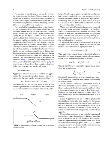
interface. The concentration gradient in both phases are
tration range, with an average slope m such that
illustrated in Fig. 3. Note that y Ai may be higher or lower
than x Ai , depending on the equilibrium curve (e.g., Fig. 2); m = y A − y ∗ A x − x A (4)
∗
A
however, y Ai is always lower than y A , and x Ai is always
higher than x A , or no mass transfer will occur. then Eqs. (2)–(4) can be combined to express K OG in terms
of k G and k L , as follows:
1. Dilute Solutions
1 1 m
= + (5)
Applying the diffusion equations to each film and approx- K OG k G k L
imating the concentration gradient linearly yields an ex-
Equation(5)statesthattheoverallresistancetomasstrans-
pression for the mass transfer rates across the films,
fer is equal to the sum of the mass transfer resistances in
N A = k G (y A − y Ai ) = k L (x Ai − x A ) (2) each of the phases.
The use of overall coefficients is convenient because it
This equation states that, for each phase, the rate of mass
eliminates the need to calculate interface concentrations.
transfer is proportional to the difference between the bulk
Note that, theoretically, this approach is valid only when
concentration and the concentration at the gas–liquid in-
a linear approximation can be used to describe the equi-
librium curve over the relevant concentration range. Fig-
ure 4 illustrates the application of this concept on an x–y
diagram.
For most applications it is not possible to quantify the
interfacial area available for mass transfer. For this reason,
data are commonly presented in terms of mass transfer co-
efficients based on a unit volume of the apparatus. Such
volumetric coefficients are denoted k G a, k L a and K OG a,
where a is the interfacial area per unit volume of the
apparatus.
If most of the resistance is known to be concentrated
in one of the phases, the resistance in the other phase can
often be neglected and Eq. (5) simplified. For instance,
when hydrogen chloride is absorbed in water, most of the
resistance occurs in the gas phase, and K OG ≈ k G . When
FIGURE 3 Concentration profiles in the vapor and liquid phases oxygen is absorbed in water, most of the resistance occurs
near an interface. in the liquid phase, and K OG ≈ k L /m.