
Page 429 - Academic Press Encyclopedia of Physical Science and Technology 3rd Analytical Chemistry
P. 429
P1: GLQ Final pages
Encyclopedia of Physical Science and Technology EN012C-568 July 26, 2001 15:32
Photoelectron Spectroscopy 79
will make the terms E A and E P more dominant. For an
intrinsically wide peak, reducing the pass energy past a
certain point will not reduce the achieved width further
and will only serve in reducing the sensitivity.
The combination of retardation and deflection allows
two different modes of operation. In the constant ana-
lyzer energy (CAE) mode the pass energy is kept constant
and the spectrum is scanned by a variation of the retard-
ing field. In this mode the resolution E A is kept con-
stant over the whole spectrum. In the constant retard ratio
mode (CRR) the voltage difference between the hemi-
spheres is proportional to the retarding field. In this mode
the relative resolution E/E is kept constant. The CAE
mode is normally used for PES, the CRR mode for Auger
spectroscopy.
An electrostatic deflection analyzer widely used in
Auger spectroscopy is the cylindrical mirror analyzer
(CMA). There are two different types of CMA, which cor-
respond to two different regimes of the angular second-
order focusing: the axis–axis and the ring–axis type fo-
cusing. A CMA with axis–axis type angular focusing, as
sketched in Fig. 17b, is composed of two coaxial cylin-
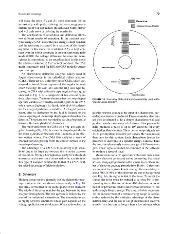
drical electrodes. The inner electrode has two ring-shaped FIGURE 18 Rear view of the channeltron assembly used in the
®
aperture windows, covered by a metallic grid. At the CMA VG ESCALAB 220iXL .
exit a receipt diaphragm is placed, behind which a detec-
tor for charged particles is installed. A charged particle
beam, after its deflection in the field is focused to the hits the resistive coating at the input of a channeltron, sec-
central opening of the receipt diaphragm and reaches the ondary electrons are produced. These secondary electrons
detector. The spectrum is recorded by varying the potential are then accelerated to hit a deeper channeltron wall and
between the two cylindrical electrodes. produce another avalanche of electrons. This process fi-
8
The major difference of a CMA with ring–axis type an- nally produces a pulse of up to 10 electrons for every
gular focusing (Fig. 17c) is a narrow ring-shaped slot in original incident electron. These pulsed output signals are
the inner cylindrical electrode that functions as an elec- fed to preamplifiers mounted just outside the vacuum and
tron optical source. The CMA thus analyzes a beam of then onto the data system. Each channeltron detects the
charged particles passing from the emitter surface to the presence of electrons in a specific energy window. Thus
ring-shaped opening. the array simultaneously covers a range of different ener-
The advantage of a CMA is its relatively high sensi- gies. These signals can then be combined in the software
tivity due to its large γ ; however, this is at the expense to produce a spectral trace.
of resolution. Fitting a hemispherical analyzer with a high Measurement of a PE spectrum with count rates down
transmission electron transfer lens makes the sensitivity of to a few electrons per second is time consuming. Statistical
this type of analyzer comparable to that of a CMA, with noise is always proportional to the square root of the num-
the added advantage of high resolution. ber of electrons counted per unit time. If only 10 electrons
are counted for a given kinetic energy, the uncertainty is
about 30%. If 90% of the electrons are due to background
E. Detectors
(see Fig. 1c), the signal is lost in the noise. To detect the
Modern spectrometers generally use multichanneltron ar- signal, the noise must be reduced to at least 5%, corre-
rays similar to the one shown schematically in Fig. 18. sponding to a collection of about 400 electrons. A count
The array is mounted in the output plane of the analyzer. rate of 10 per second leads to an observation time of 40 sec
The width of the array matches the gap between the two at this single kinetic energy. The time, which is necessary
analyzer hemispheres. The exit aperture is defined by the for the measurement of a certain energy range, is consid-
area of the individual channeltron. The channeltrons act erably reduced by the multiplex advantage of the chan-
as highly sensitive amplifiers whose gain depends on the neltron array and the use of a high transmission electron
voltage applied across the detector. When a photoelectron transfer lens but can be longer than a few minutes when