
Page 34 - Subyek Encyclopedia - Encyclopedia of Separation Science
P. 34
Sepsci*11*TSK*Venkatachala=BG
I / CENTRIFUGATION 29
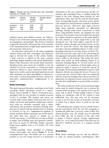
Table 2 Strength data for commonly used rotor construction orientation as the rotor speed increases. In this ori-
materials (from Sheeler, 1981) entation, the centrifugal force is applied along the
length of the tube, making them suitable for rate
Material Density Ultimate Strength: density
(gcm ) strength ratio separations. They may also be used for batch separ-
3
3
(gcm ) ation of immiscible liquids with some rotors speciR-
cally designed to hold separatory funnels to facilitate
Aluminium 2.79 2159 774 post-run recovery. However, their high k-factors
Titanium 4.84 6088 1258 make them generally unsuitable for differential
Steel 7.99 7915 991
pelleting, though some rotors constructed to hold
short, large-diameter bottles, are designed for such
purposes. Fixed-angle rotors are loaded and operated
cellulose nitrate and cellulose acetate, etc. Polycar- in a similar manner except that, as the name implies,
bonate is one of the more popular materials owing to the tube remains at a Rxed angle both at rest and
its transparency and strength. The choice of material during the run. The Rxed angle is typically 20}453
is generally dictated by the properties of the particles from the vertical, though near-vertical rotors are less
to be fractionated and, in high speed separations, by than 103 from the vertical. The Rxed-angle design
the maximum rated g force. provides a shorter pathlength (Figure 7) with a corre-
An exhaustive discussion of the many equipment sponding reduction in run time (lower k-factor). Par-
options along with their advantages and disadvan- ticles that reach the outer wall of the tube during the
tages is beyond the scope of this article. Rather, run aggregate and quickly slide down the tube wall to
a brief overview is offered of the more common form a pellet in the bottom. This makes the Rxed-
centrifuge designs together with typical applications. angle rotor useful for both pelleting (Figure 3) or
Much of the discussion will assume batch operation, isopycnic banding (Figure 4). Vertical rotors can be
though in most cases rotors are available or may be considered as an extension of Rxed-angle rotors in
adapted for batch, semi-batch or continuous-mode which the angle of repose is 03 from the vertical. In
operation. However, since continuous-mode centri- this design, the maximum pathlength is equal to tube
fuges are so widely used in industrial applications and diameter, thereby providing the lowest k-factors for
their analogues are often unavailable in laboratory- a given tube size. Vertical tube rotors are commonly
scale units, a section describing the more common or used for isopycnic banding where short run times are
innovative continuous-Sow conRgurations is in- important, as compared to near-vertical rotors, which
cluded. provide short pathlengths yet permit pellet accumula-
tion.
Bottle Centrifuges
The tubes loaded into both vertical and Rxed-angle
The most common laboratory centrifuge is the bottle rotors must be sealed during the run to prevent the
centrifuge. Bottle centrifuges consist of a motor- contents from escaping as the medium moves up the
driven vertical spindle to which a horizontal rotor, outer wall at speed. O-ring sealing systems or heat
machined with an even number of sample positions sealing are commonly used. If the volume is kept
(2}36), is attached. The harness and rotors are sufRciently low, this step may not be necessary
covered with a safety shield, which may also serve to except to prevent the escape of hazardous aerosols,
reduce air friction and facilitate temperature control. in which case a plastic screw or push-on cap may
Such units are normally equipped with a timer, sufRce.
tachometer, and manual or automatic braking. Sam- For pelleting runs, sample recovery entails decant-
ples may be mixed with the medium prior to loading, ing the supernatant from the top and scrapping or
or layered on top of a homogeneous medium or washing the pellet into a recovery vessel or Rlter. For
density gradient. Bottle centrifuges are usually bench- density-gradient runs, the sample may be unloaded
top units that may operate at speeds up to from either the top or bottom of the tube with
30 000 rpm and g max of 65 000, but are also available a pump, a Pasteur pipette, syringe, displacement
as larger, free-standing units that generate centrifu- liquid, etc., or by using soft plastic tubes that may be
gal forces in excess of 100 000g. Sample capacities pierced to facilitate recovery of a targeted central
range from capillary tube to 1 L bottles (4 L total band.
capacity).
Bottle-centrifuge rotors classiRed as swinging-
bucket, Rxed-angle, and vertical (Figure 7). In the Zonal Rotors
swinging-bucket type, the bottles are in a vertical While bottle centrifuges can be, and are, effective-
position at rest but swing outward to a horizontal ly used for density-gradient centrifugation, their