
Page 38 - Subyek Encyclopedia - Encyclopedia of Separation Science
P. 38
Sepsci*11*TSK*Venkatachala=BG
I / CENTRIFUGATION 33
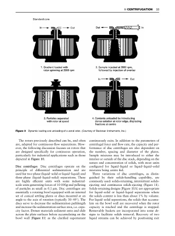
Figure 9 Dynamic loading and unloading of a zonal rotor. (Courtesy of Beckman Instruments, Inc.)
The rotors previously described can be, and often continuously exits. In addition to the parameters of
are, adapted for continuous-Sow separations. How- centrifugal force and Sow rate, the capacity and per-
ever, the following discussion focuses on rotors that formance of disc centrifuges are also dependent on
are designed speciRcally for continuous operation, the number, spacing and diameter of the plates.
particularly for industrial applications such as those Sample mixtures may be introduced to either the
depicted in Figure 10. interior or outside of the disc stack, depending on the
nature and concentration of solids, with most units
Disc centrifuges Disc centrifuges operate on the conRgured for liquid}liquid or liquid}liquid}solid
principle of differential sedimentation and are mixtures being centre fed.
used for two-phase (liquid}solid or liquid}liquid) and Three variations of disc centrifuges, as distin-
three-phase (liquid}liquid}solid) separations. These guished by their solids-handling capability, are
are highly efRcient units with some industrial- commonly used: solids-retaining, intermittent solids-
scale units generating forces of 10 000g and pelleting ejecting and continuous solids-ejecting (Figure 11).
of particles as small as 0.1 m. Disc centrifuges are Solids-retaining designs (Figure 11A) are appropriate
essentially a rotating bowl equipped with an internal for liquid}solid or liquid}liquid separations where
set of conical settling plates or discs mounted at an the solids content is less than about 1% by volume.
angle to the axis of rotation (typically 30}403). The For liquid}solid separations, the solids that accumu-
discs serve to decrease the sedimentation pathlength late on the bowl wall are recovered when the rotor
and increase the sedimentation surface area, i.e. capa- capacity is reached and the centrifuge is stopped.
city factor. Denser materials sediment onto and slide Removable baskets are incorporated into some de-
across the plate surfaces before accumulating on the signs to facilitate solids removal. Recovery of two
bowl wall (Figure 11) as the clariRed supernatant liquid streams can be achieved by positioning exit