
Page 42 - Subyek Encyclopedia - Encyclopedia of Separation Science
P. 42
Sepsci*11*TSK*Venkatachala=BG
I / CENTRIFUGATION 37
1
diameters of 4.5 cm, throughput rates of 150 L h ,
and centrifugal forces ranging up to 62 000g. Because
of their high speed and short settling path, tubular
centrifuges are well suited for the pelleting of ultraRne
particles, liquid clariRcation, and separation of dif-
Rcult-to-separate immiscible liquids. In addition to
the standard electric motor used for most laboratory
centrifuges, laboratory-scale tubular centrifuges are
available with turbine drives. Tubular centrifuges
were reRned for the separation of penicillin during
World War II but since then have largely been re-
placed by disc centrifuges because of their limited
holding capacity. However, they are still widely used
for applications that involve the efRcient recovery
of high value products at high purity, especially in the
pharmaceutical and chemical industries. Typical
applications include recovery of Escherichia coli cells
and Su viruses, removal of colloidal carbon and
moisture from transformer oils, removal of small par-
ticles from lubricating oils, blood fractionation, and
de-inking.
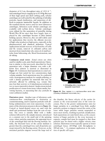
Continuous zonal rotors Zonal rotors are often
used for smaller scale, semi-batch separations. Opera-
tion is similar to that previously described for batch
separation only a larger diameter core with a dif-
ferent Sow pattern is inserted as illustrated in
Figure 15. Continuous-feed separations in zonal cen-
trifuges are best suited for low concentration, high
volume samples. Such separations may be conducted
with a homogeneous medium for sample pelleting, or
with a density gradient for materials that may be
adversely affected by pelleting (e.g. viruses that
may lose their activity) or if simultaneous isolation of
two or more materials is desired. Applications include
puriRcation of viruses from tissue-culture media, har-
vesting bacteria, or separating Rne clay particles in Figure 15 Flow regimes in a continuous-flow zonal rotor.
water pollution studies. (Courtesy of Beckman Instruments, Inc.)
Elutriation rotors Another type of laboratory-scale
continuous-Sow centrifugation is elutriation or the chamber, the linear velocity of the carrier de-
counterstreaming, used to separate particles with dif- creases as the cross-sectional area of the rotor in-
fering sedimentation rates (rate separation). A sche- creases. Due to the greater sedimentation rates for
matic of the elutriation process is shown in Figure 16. larger particles in a centrifugal force Reld, smaller
Conical or funnel-shaped rotors are used with the particles continue to migrate toward the centre of the
small end positioned farthest from the axis of rota- rotor while larger particles remain suspended or
tion. The rotor is initially Rlled with a buffer move more slowly, resulting in particle classiRcation.
solution followed by the sample mixture, introduced Such separations are semi-batch since, as the concen-
at a constant rate to the small end of the spinning tration of larger particles in the rotor increases to
rotor, where particles experience the opposing forces capacity, sample feed must be stopped so that these
of the centrifugal Reld and the Sowing medium. Ini- particles may be eluted with a higher velocity rinse
tially, the frictional force of the carrier medium is solution. Elutriation rotors typically operate at lower
greater than the centrifugal force and all particles are centrifugal forces (10 000g) with throughputs to
1
swept inward by the Sowing carrier. However, as the 400 mL min . A common application is the isola-
entrained particles migrate toward the large end of tion of speciRc cell types.