
Page 36 - Subyek Encyclopedia - Encyclopedia of Separation Science
P. 36
Sepsci*11*TSK*Venkatachala=BG
I / CENTRIFUGATION 31
can be operated in batch, semi-batch, or continuous Ultracentrifuges
modes and may be loaded or unloaded with the
rotor stopped (static) or with the rotor spinning (dy- ‘Ultracentrifuge’ is an ill-deRned term applied to cen-
namic). trifuges with rated speeds greater than about
Statically loaded and unloaded zonal rotors are 25 000 rpm, regardless of the medium or rotor de-
also called reorienting gradient rotors. In this sign. While speed was historically used to designate
method, the gradient is loaded with the rotor at rest ultracentrifugation, some manufactures now reserve
then slowly accelerated to permit the gradient to this term for centrifuges that operate at sufRcient
reorient from a horizontal to a vertical conRguration, speeds to require a vacuum to reduce frictional drag
as illustrated in Figure 8. Solutions of increasing den- and/or rotor heating. Most such units are also
sity are loaded to the bottom with the sample solution equipped with refrigerant capability for the same
layered on top after the rotor is Rlled. When the rotor purpose.
is accelerated, the gradient reorientates to a vertical Ultracentrifuges are classiRed as preparative or
position with the lighter fractions and sample in the analytical. Preparative ultracentrifuges are used to
centre of the rotor. After centrifugation, the rotor is separate and recover puriRed sample components at
slowly decelerated and the gradient returns to a hori- speeds ranging up to 150 000 rpm and forces to
zontal orientation. The heavier fractions may be re- 900 000g. The rotor conRguration may be any of the
moved Rrst by displacement with air or the rotor lid types described in this section } bottle, zonal, or
removed and the gradient pumped out. Alternatively, continuous } with Rxed-angle and vertical-bottle cen-
the gradient may be displaced with a denser liquid trifuges providing the highest speeds and titanium
that forces the lighter fractions out Rrst. The ad- being the most common material of construction.
vantages of the reorienting gradient technique are Analytical ultracentrifuges, originally developed by
simplicity and the avoidance of rotating seals that Svedberg, are used to study the behaviour of particles
may leak or fail during dynamic loading/unloading. during sedimentation. While analytical rotors are
The major disadvantage is the tendency of the gradi- available in various shapes and sizes, their deRning
ent to swirl as it reorients, leading to a loss in resolu- feature is a transparent window, typically constructed
tion. of quartz or sapphire, that permits the sedimenting
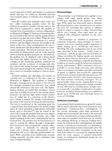
Dynamic loading and unloading, also known as particles to be monitored optically during the run. UV
‘rotating seal’, is conducted as the rotor spins, as absorption and/or refractive index measurements are
illustrated in Figure 9. The gradient is pumped the most common monitoring techniques. The re-
through a rotating seal in the centre of the rotor lid quired sample volume is low, ranging down to 5 L,
into passages machined into the rotor core, which making this a useful technique when sample availabil-
channel the solutions to the outer wall. The lighter- ity may otherwise be a limiting factor. Sample recov-
density solutions are loaded Rrst, forming a vertical ery is generally a secondary consideration, if conduc-
layer that is displaced inward by the ensuing denser ted at all. Analytical ultracentrifuges are available at
solutions. An optional high density liquid cushion speeds up to 70 000 rpm and centrifugal forces in
may be added last if a reduction in the effective excess of 350 000g.
rotor volume is desired. The sample is introduced to
the centre of the rotor by reversing the feed/exit lines. Continuous Centrifuges
The rotor is accelerated to the operating speed for Conventional batch separations are generally unsuit-
a targeted time, then decelerated to the initial loading able for many industrial and certain laboratory-scale
speed. In centre unloading, a high density immiscible separations. Continuous-Sow centrifugation of-
liquid, such as Fluorinert , may be routed to the fers certain advantages when large quantities of
outer wall, forcing the gradient from the rotor, lighter sample must be processed, the stream to be recovered
fractions Rrst. Edge unloading is similar, only a light is at low concentration, or long acceleration/deceler-
liquid is pumped to the centre, displacing the heavier ation times are required. Such units may be used for
fractions Rrst. The gradient may be fractionated as it rate, pelleting, Rltration, or isopycnic banding separ-
exits by routing the efSuent through a programm- ations. In continuous-Sow centrifugation, the sample
able fractionator that automatically switches collec- mixture is introduced continuously to a spinning ro-
tion vessels, or manually by selecting cutoff tor as the supernatant stream continuously exits. The
points with a density meter, refractometer or UV denser product may either accumulate on the rotor
absorption cell, or by collecting predetermined vol- wall, from where it is recovered by stopping the run
umes. While somewhat more cumbersome, dynamic when the rotor capacity is reached (semi-batch
loading generally provides better resolution than mode), or continuously discharged during the run
static loading/unloading. (continuous mode).