
Page 194 - Energy from Toxic Organic Waste for Heat and Power Generation
P. 194
172 Energy from Toxic Organic Waste for Heat and Power Generation
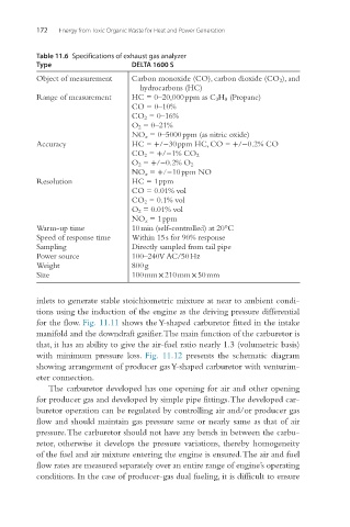
Table 11.6 Specifications of exhaust gas analyzer
Type DELTA 1600 S
Object of measurement Carbon monoxide (CO), carbon dioxide (CO 2 ), and
hydrocarbons (HC)
Range of measurement HC = 0–20,000 ppm as C 3 H 8 (Propane)
CO = 0–10%
CO 2 = 0–16%
O 2 = 0–21%
NO x = 0–5000 ppm (as nitric oxide)
Accuracy HC = +/−30 ppm HC, CO = +/−0.2% CO
CO 2 = +/−1% CO 2
O 2 = +/−0.2% O 2
NO x = +/−10 ppm NO
Resolution HC = 1 ppm
CO = 0.01% vol
CO 2 = 0.1% vol
O 2 = 0.01% vol
NO x = 1 ppm
Warm-up time 10 min (self-controlled) at 20°C
Speed of response time Within 15 s for 90% response
Sampling Directly sampled from tail pipe
Power source 100–240 V AC/50 Hz
Weight 800 g
Size 100 mm × 210 mm × 50 mm
inlets to generate stable stoichiometric mixture at near to ambient condi-
tions using the induction of the engine as the driving pressure differential
for the flow. Fig. 11.11 shows the Y-shaped carburetor fitted in the intake
manifold and the downdraft gasifier. The main function of the carburetor is
that, it has an ability to give the air-fuel ratio nearly 1.3 (volumetric basis)
with minimum pressure loss. Fig. 11.12 presents the schematic diagram
showing arrangement of producer gas Y-shaped carburetor with venturim-
eter connection.
The carburetor developed has one opening for air and other opening
for producer gas and developed by simple pipe fittings. The developed car-
buretor operation can be regulated by controlling air and/or producer gas
flow and should maintain gas pressure same or nearly same as that of air
pressure. The carburetor should not have any bends in between the carbu-
retor, otherwise it develops the pressure variations, thereby homogeneity
of the fuel and air mixture entering the engine is ensured. The air and fuel
flow rates are measured separately over an entire range of engine’s operating
conditions. In the case of producer-gas dual fueling, it is difficult to ensure