
Page 190 - Energy from Toxic Organic Waste for Heat and Power Generation
P. 190
Power Generation From Renewable Energy Sources 169
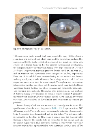
Fig. 11.10 Photographic view of HCC and RCC.
100 consecutive cycles at each load were recorded in steps of 20 cycles at a
given time and averaged out values were used for combustion analysis. The
engine used for the study consists of mechanical fuel injection system with
3 holes of 0.25 mm diameter. For the present experimental investigation,
the compression ratio and injection timing were kept constant at 17.5 and
27° bTDC, respectively. Injection pressures for the diesel-PG, HOME-PG,
and HOME+FO-PG operations were changed to 230 bar, respectively.
Flow rate of air and fuel were measured using air box method and burette
and stop watch, respectively. Minimum five readings were recorded and av-
eraged out values were used for result analysis. Throughout the experimen-
tal campaign, the flow rate of gas and the engine speed were fixed. Problems
were faced during the flow rate of gas measurement because the gas quality
was changing intermittently. Hence, for each measurement, five readings
at different timing were recorded to obtain a reliable average. A piezoelec-
tric transducer (make: PCB Piezotronics, model: HSM 111A22, resolution:
0.145 mV/kPa) was fitted to the cylinder head to measure in-cylinder gas
pressure.
Smoke density of exhaust was measured by Hartridge smoke meter. The
specification of smoke meter is given in Table 11.5. It operates from 24 V
AC power supply. The smoke meter works on the principle of comparative
basis. It contains two dimensional and optical tubes. The reference tube
is connected to the clean air blower. Air is drawn from the clean air inlet
through a damper. The smoke tube is connected to the smoke inlet via
the smoke bypass valve. This inlet track contains a temperature sensor and
moisture trap and has a pressure relief valve controlled outlet, a pick-off for