
Page 188 - Energy from Toxic Organic Waste for Heat and Power Generation
P. 188
Power Generation From Renewable Energy Sources 167
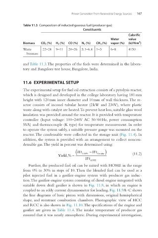
Table 11.3 Composition of inducted gaseous fuel (producer gas)
Constituents
Calorific
Water value
3
Biomass CO 2 (%) H 2 (%) CO (%) N 2 (%) CH 4 (%) vapor (%) (kJ/N m )
Waste 22–24 9–11 20–26 5.1–6.4 1–3 6–8 4150
biomass
and Table 11.3.The properties of the fuels were determined in the labora-
tory and Bangalore test house, Bangalore, India.
11.6 EXPERIMENTAL SETUP
The experimental setup for fuel oil extraction consists of a pyrolysis reactor,
which is designed and developed in the college laboratory having 181 mm
height with 120 mm inner diameter and 10 mm of wall thickness. The re-
actor consists of inconel tubular heater (2 kW and 230 V), where plastic
waste along with catalyst are heated. To prevent heat loss, suitable glass wool
insulation was provided around the reactor. It is provided with temperature
controller (Input voltage: 100–240 V AC 50/60 Hz, power consumption
5 VA) and thermocouple (K type) for temperature measurement. In order
to operate the system safely, a suitable pressure gauge was mounted on the
reactor. The condensable were collected in the storage unit (Fig. 11.4). In
addition, the system is provided with an arrangement to collect noncon-
densable gas. The yield in percent was determined using:
(Wt LDPE −Wt Re ) (11.2)
sidue
Yield,% =
Wt LDPE
Further, the produced fuel oil can be mixed with HOME in the range
from 0% to 30% in steps of 10. Then the blended fuel can be used as a
pilot injected fuel in a gasifier-engine system with producer gas induc-
tion. The gasifier-engine system consisting of diesel engine integrated with
suitable down draft gasifier is shown in Fig. 11.8, in which an engine is
coupled to an eddy current dynamometer for loading. Fig. 11.9A–C shows
the line diagrams of basic piston with dimensions, original hemispherical
shape, and reentrant combustion chambers. Photographic view of HCC
and RCC is also shown in Fig. 11.10. The specifications of the engine and
gasifier are given in Table 11.4. The intake temperature of producer gas
ensured that it was nearly atmospheric. During experimental investigation,