
Page 184 - Energy from Toxic Organic Waste for Heat and Power Generation
P. 184
164 Energy from Toxic Organic Waste for Heat and Power Generation
Table 11.1 Physical characterization of oil
Temp (°C) Carbon range Fraction
Upto 130 C 6 –C 10 Gasoline
130–170 C 6 –C 10 Naphtha
170–230 C 11 –C 12 Kerosene (paraffin) oil
230–320 C 13 –C 17 Light gas oil (high-speed diesel component)
320–380 C 18 –C 25 Heavy gas oil (high-speed diesel component)
>380 >C 25 Reduced crude oil
11.4 DOWN DRAFT GASIFIER FOR PRODUCTION OF
PRODUCER GAS
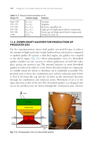
For the experimentation, down draft gasifier was used because it reduces
the amount of high-molecular weight hydrocarbons and particles compared
to updraft gasifier. To operate a dual fuel engine, the gasifier was coupled
to the diesel engine. Fig. 11.6 shows photographic view of a downdraft
gasifier. Gasifiers are the reactors in which gasification of solid fuel takes
place giving out producer gas. The internal diameter in most downdraft
gasifiers is reduced in order to create throat. Air inlet nozzles are commonly
set radially round the throat to distribute air as uniformly as possible. The
pyrolysis zone is above the combustion zone and the reduction zone below
it. Fuel is fed from the top and the air flows in the downward direction
through the combustion and reduction zones. Movement of air is in the
same direction as that of the fuel. The downdraft gasifier is so designed that
tars in the pyrolysis zone are drawn through the combustion zone wherein
Fuel
Filter
Hopper
Drying zone
Pyrolysis zone
Air Combustion Air
zone
Reduction zone
Grate
Producer
gas
Fig. 11.6 Photographic view of a downdraft gasifier.