
Page 196 - Energy from Toxic Organic Waste for Heat and Power Generation
P. 196
174 Energy from Toxic Organic Waste for Heat and Power Generation
Venturimeter
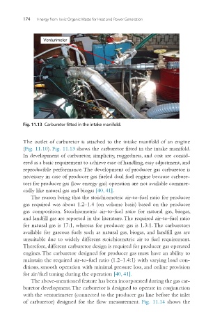
Fig. 11.13 Carburetor fitted in the intake manifold.
The outlet of carburetor is attached to the intake manifold of an engine
(Fig. 11.10). Fig. 11.13 shows the carburetor fitted in the intake manifold.
In development of carburetor, simplicity, ruggedness, and cost are consid-
ered as a basic requirement to achieve ease of handling, easy adjustment, and
reproducible performance. The development of producer gas carburetor is
necessary in case of producer gas fueled dual fuel engine because carbure-
tors for producer gas (low energy gas) operation are not available commer-
cially like natural gas and biogas [40, 41].
The reason being that the stoichiometric air-to-fuel ratio for producer
gas required was about 1.2–1.4 (on volume basis) based on the producer
gas composition. Stoichiometric air-to-fuel ratio for natural gas, biogas,
and landfill gas are reported in the literature. The required air-to-fuel ratio
for natural gas is 17:1, whereas for producer gas is 1.3:1. The carburetors
available for gaseous fuels such as natural gas, biogas, and landfill gas are
unsuitable due to widely different stoichiometric air to fuel requirement.
Therefore, different carburetor design is required for producer gas operated
engines. The carburetor designed for producer gas must have an ability to
maintain the required air-to-fuel ratio (1.2–1.4:1) with varying load con-
ditions, smooth operation with minimal pressure loss, and online provision
for air/fuel tuning during the operation [40, 41].
The above-mentioned feature has been incorporated during the gas car-
buretor development. The carburetor is designed to operate in conjunction
with the venturimeter (connected to the producer gas line before the inlet
of carburetor) designed for the flow measurement. Fig. 11.14 shows the