
Page 191 - Engineered Interfaces in Fiber Reinforced Composites
P. 191
Chapter 5. Surface treatments ofjibers and effects on composite properties 173
charqe to furnace
I=&)
traverse
spool
I
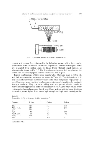
Fig. 5.2. Schematic diagram of glass fiber manufacturing.
ceramic and organic fibers discussed in the following sections. Glass fibers can be
produced in either continuous filament or staple form. The continuous glass fibers
are generated from molten glass by being drawn through small orifices, as
schematically shown in Fig. 5.2. The fiber diameter is controlled by adjusting the
orifice size, the winding speed and the viscosity of molten glass.
Typical combinations of three most popular glass fibers are given in Table 5.1,
and their representative properties are shown in Table 5.2. The designations E, C
and S stand for electrical, chemical/corrosion and structural grades, respectively. E-
glass fibers are a good electrical insulator, possessing good strength and a moderate
Young's modulus. They are most widely used for printed circuit boards in
microelectronic applications and boat hull constructions. C-glass fibers have a better
resistance to chemical corrosion than E-glass fibers, and are suitable for applications
in chemical plants. S-glass fibers have a high strength and high modulus designed for
Table 5.1
Composition (wtX) of glass used for fiber manufacture"
Elements E - g I a s s C - g I a s s S-glass
Si02 52.4 64.4 64.4
A1~03, Fez03 14.4 4.1 25.0
CaO 17.2 13.4 -
MgO 4.6 3.3 10.3
Na20, K20 0.8 9.6 0.3
Ba203 10.6 4.7 -
BaO - 0.9 -
aAfter Hull (1981).