
Page 354 - Engineered Interfaces in Fiber Reinforced Composites
P. 354
Chapter 8. Improvement of interlaminar fructure toughness with interfuce control 335
because the realization of full resistance to delamination provided by thc matrix is
only possible when the resin deformation is not preempted by interfacial bonding.
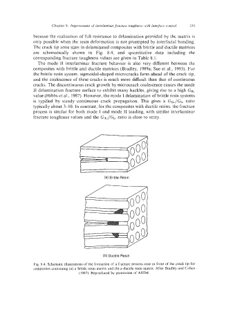
The crack tip zone sizes in delaminated composites with brittle and ductile matrices
are schematically shown in Fig. 8.4, and quantitative data including the
corresponding fracture toughness values are given in Table 8.1.
The mode I1 interlaminar fracture behavior is also very different between the
composites with brittle and ductile matrices (Bradley, 1989a; Sue et al., 1993). For
the brittle resin system. sigmoidal-shaped microcracks form ahead of the crack tip,
and the coalescence of these cracks is much more difficult than that of continuous
cracks. The discontinuous crack growth by microcrack coalescence causes the mode
11 delamination fracture surface to exhibit many hackles, giving rise to a high G1lc
value (Hibbs et al., 1987). However, the mode I delamination of brittle resin systems
is typified by steady continuous crack propagation. This gives a G1lc/Glc ratio
typically about 3-10. In contrast, for the composites with ductile resins, the fracture
process is similar for both mode I and mode 11 loading, with similar interlaminar
fracture toughness values and the G1lc/Glc ratio is close to unity.
_v
(a) Brittle Resin
(b) Ductile Resin
Fig. 8.4. Schematic illustrations of the formation of a fracture process zone in front of the crack tip for
composites containing (a) a brittle resin matrix and (b) a ductile resin matrix. After Bradley and Cohen
(1987). Reproduced by permission of ASTM.