
Page 355 - Engineered Interfaces in Fiber Reinforced Composites
P. 355
336 Engineered interfaces in $her reinforced composiies
Table 8.1
Damage zone size in mode I fracture and corresponding interlaminar fracture toughness values, G;; and
qIc, carbon fiber-epoxy matrix composites".
of
System (Fiber/matrix) V, (%) Mode I damage zone size Fracture toughness (kJ/m2)
ahead of above/below G;", GFC GFlc
crack (pn) crack (jm)
AS413502 76 20 5 0.07 0.19 0.57
T3T145iF155 NR 54 20 7 0.167 0.335 1.66
T3T145/F155 60 30 20 0.73 1.015 2.06
T3T145/F155 69 20 10 0.73 0.52 1.27
T3T145/Fl55 71 20 10 0.73 0.615 1.80
T3T145/F185 NR 58 75 35 0.46 0.455 I .05
T3T 145/F185 57 200 35 5.0 1.73 2.44
'After Jordan et al. (1989).
V, fiber volume fraction; G& neat resin fracture toughness; cf;, mode I interlaminar fracture toughness
of composite; qlC. mode I1 interlaminar fracture toughness of composite.
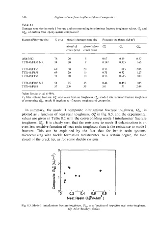
In summary, the mode I1 composite interlaminar fracture toughness, qrc,
is
plotted as a function of neat resin toughness, cf", in Fig. 8.5, and the experimental
values are given in Table 8.2 with the corresponding mode I interlaminar fracture
toughness, qc. It is clearly seen that the resistance to mode I1 delamination is an
even less sensitive function of neat resin toughness than is the resistance to mode I
fracture. This can be explained by the fact that for brittle resin systems,
microcracking with hackle formation redistributes, to a certain degree, the load
ahead of the crack tip, as for some ductile systems.
"0 0.2 0.4 0.6 0.8
Neat Resin GlF (kJ/m2 )
Fig. 8.5. Mode I1 interlaminar fracture toughness. Glc, as a function of respective neat resin toughness,
q. After Bradley (1989a).