
Page 167 - Engineering Digital Design
P. 167
138 CHAPTER 4 / LOGIC FUNCTION REPRESENTATION AND MINIMIZATION
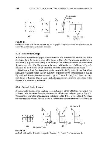
Minterm code
v i numbers
A\ //
m ; 4 0 1
0 M
m 0 0
/
\ 0 1
m 1
A = m i 1 \ /
Minterm code
numbers
FIGURE 4.5
(a) Minterm code table for one variable and (b) its graphical equivalent, (c) Alternative formats for
first order K-maps showing minterm positions.
4.3.1 First-Order K-maps
A first-order K-map is the graphical representation of a truth table of one variable and is
developed from the minterm code table shown in Fig. 4.5a. The minterm positions in a
first-order K-map are shown in Fig. 4.5b, leading to the alternative formats for a first-order
K-map given in Fig. 4.5c. The number in the lower right-hand corner of a K-map in Fig. 4.5c
indicates the position into which a minterm with that code number must be placed.
Consider the three functions given by the truth tables in Fig. 4.6a. Notice that all in-
formation contained within a given truth table is present in the corresponding K-map in
Fig. 4.6b and that the functions are read as f\ = X, / 2 = X, and /3 = 1 from either the
truth tables or K-maps. Thus, a logic 1 indicates presence of a minterm and a logic 0 (the
absence of a minterm) is a maxterm.
4.3.2 Second-Order K-maps
A second-order K-map is the graphical representation of a truth table for a function of two
variables and is developed from the minterm code table for two variables given in Fig. 4.7a.
The graphical equivalent of the minterm code table in Fig. 4.7a is given in Fig. 4.7b, where
the minterm code decimal for each of four m, is the binary equivalent of the cell coordinates
r— All that is X
x\ /' x\
0 0 1 0 1
X fl f f 3 0 0 0
z
0 0 1 1 1 1 0 1 1
1 1 0 1 4 1 1 / - 1
"7f, = X ' 7f 2 = X ' 7f 3 = 1
<a> (b)
All that is X^
FIGURE 4.6
(a) Truth table and (b) first order K-maps for functions f\, />, and /3 of one variable X.