
Page 172 - Engineering Digital Design
P. 172
4.3 INTRODUCTION TO LOGIC FUNCTION GRAPHICS 143
CD C \ AB
AB\ 00 01 ' 11 10 ' CD\ 00 01 ' 11 10
\J 1
\J\J
00 00
0 1 3 2 0 4 12 8 — ,
01 01
4 5 7 6 1 5 13 9
11 11
12 13 15 14 3 7 15 11
10 10
8 9 11 10 2 6 14 10 /
D B
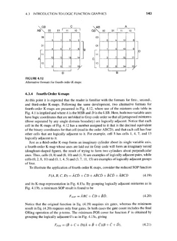
FIGURE 4.12
Alternative formats for fourth-order K-maps.
4.3.4 Fourth-Order K-maps
At this point it is expected that the reader is familiar with the formats for first-, second-,
and third-order K-maps. Following the same development, two alternative formats for
fourth-order K-maps are presented in Fig. 4.12, where use of the minterm code table in
Fig. 4.1 is implied and where A is the MSB and D is the LSB. Here, both two-variable axes
have logic coordinates that are unfolded in Gray code order so that all juxtaposed minterms
(those separated by any single domain boundary) are logically adjacent. Notice that each
cell in the K-maps of Fig. 4.12 has a number assigned to it that is the decimal equivalent
of the binary coordinates for that cell (read in the order ABCD), and that each cell has four
other cells that are logically adjacent to it. For example, cell 5 has cells 1, 4, 7, and 13
logically adjacent to it.
Just as a third-order K-map forms an imaginary cylinder about its single variable axis,
a fourth-order K-map whose axes are laid out in Gray code will form an imaginary toroid
(doughnut-shaped figure), the result of trying to form two cylinders about perpendicular
axes. Thus, cells (0, 8) and (8, 10) and (1, 9) are examples of logically adjacent pairs, while
cells (0, 2, 8,10) and (0, 1, 4, 5) and (3, 7, 11, 15) are examples of logically adjacent groups
of four.
To illustrate the application of fourth-order K-maps, consider the reduced SOP function
F(A, B, C,D)=ACD + CD + ABCD + BCD + ABCD (4.19)
and its K-map representation in Fig. 4.13a. By grouping logically adjacent minterms as in
Fig. 4.13b, a minimum SOP result is found to be
F SOP=ABC+CD + BD. (4.20)
Notice that the original function in Eq. (4.19) requires six gates, whereas the minimum
result in Eq. (4.20) requires only four gates. In both cases the gate count includes the final
ORing operation of the p-terms. The minimum POS cover for function F is obtained by
grouping the logically adjacent O's as in Fig. 4.13c, giving
Fp OS = (B + C + D)(A + B + C)(fi + C + D), (4.21)