
Page 183 - Engineering Digital Design
P. 183
154 CHAPTER 4/LOGIC FUNCTION REPRESENTATION AND MINIMIZATION
s H E
BC i 1 .BC i 1 N.BC i 1
;\ oo 01 11 10 ' £\; oo 01 11 10 A\ °0 01 11 10
0 o (D 0 (D
0 1 3 2 0 1 3 2 0 1 3 2
1 ~T) (T~ A 1 ^> (T~ A 1 (1) 1J 01
4 5 7 6 / 4 5 7 6 / 4 5 7 6 /
/fx'f. / f,'f, I /fvf
C c C
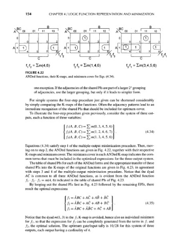
f^ 2 = Im(4,6) f 2-f 3 = Sm(1,4,6) f 3-f 1 = 2m(3,4,5,6)
FIGURE 4.22
ANDed functions, their K-maps, and minimum cover for Eqs. (4.34).
one exception. If the adjacencies of the shared Pis are part of a larger 2" grouping
of adjacencies, use the larger grouping, but only if it leads to simpler form.
For simple systems the four-step procedure just given can be shortened considerably
by simply comparing the K-maps of the functions. Often the adjacency patterns lead to an
immediate recognition of the shared Pis that should be included for optimum cover.
To illustrate the four-step procedure given previously, consider the system of three out-
puts, each a function of three variables:
,C) = £>(0,3,4,5,6)
,C) = £m(l,2,4,6,7) (4.34)
f 3(A, fl, C) = £ w(l, 3, 4, 5, 6)
Equations (4.34) satisfy step 1 of the multiple-output minimization procedure. Then, mov-
ing on to step 2, the ANDed functions are given in Fig. 4.22, together with their respective
K-maps and minimum cover. The minimum cover in each ANDed K-map indicates the com-
mon terms that must be included in the optimized expressions for the three-output system.
The table of shared Pis for each of the ANDed forms and the appropriate transfer of these
shared Pis into the K-maps of the original functions are given in Fig. 4.23, in agreement
with steps 3 and 4 of the multiple-output minimization procedure. Notice that the dyad
AC is common to all three ANDed functions, as is evident from the ANDed function
/i • /2 • /3 = m(4, 6) indicated in the table of shared Pis of Fig. 4.23.
By looping out the shared Pis first in Fig. 4.23 followed by the remaining EPIs, there
result the optimal expressions
/i = ABC + AC + AB + BC
(4.35)
/ 3 = ABC + ABC + AC + AB
Notice that the dyad m(l, 3) in the /3 K-map is avoided, hence also an individual minimum
for / 3, so that the expression for / 3 can be completely generated from the terms in f\ and
/2, the optimal solution. The optimum gate/input tally is 10/28 for this system of three
outputs, each output having a cardinality of 4.