
Page 185 - Engineering Digital Design
P. 185
156 CHAPTER 4/LOGIC FUNCTION REPRESENTATION AND MINIMIZATION
CD
AB\ 00 01 ' 11 10
00
Table of
Shared Plsforf 1+f 2
01
A+B+C
A+C+D
11
12 15 14 B+C
A
10
ho/
(a)
(b)
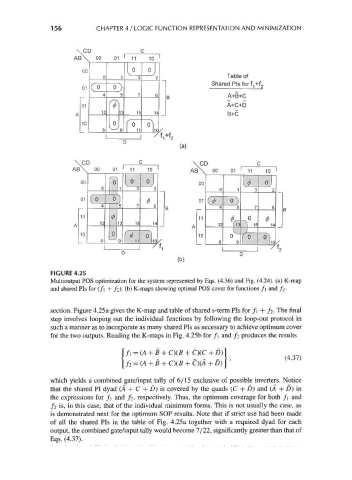
FIGURE 4.25
Multioutput POS optimization for the system represented by Eqs. (4.36) and Fig. (4.24). (a) K-map
and shared Pis for (/] + /2). (b) K-maps showing optimal POS cover for functions f\ and /2.
section. Figure 4.25a gives the K-map and table of shared s-term Pis for f\ + / 2. The final
step involves looping out the individual functions by following the loop-out protocol in
such a manner as to incorporate as many shared Pis as necessary to achieve optimum cover
for the two outputs. Reading the K-maps in Fig. 4.25b for f\ and / 2 produces the results
|/, = (A +B + CKB + C)(C +D)|
/2 = (A + B + C)(B + C)(A + D) '
which yields a combined gate/input tally of 6/15 exclusive of possible inverters. Notice
that the shared PI dyad (A + C + D) is covered by the quads (C + D) and (A + D) in
the expressions for /] and / 2, respectively. Thus, the optimum coverage for both f\ and
/ 2 is, in this case, that of the individual minimum forms. This is not usually the case, as
is demonstrated next for the optimum SOP results. Note that if strict use had been made
of all the shared Pis in the table of Fig. 4. 25 a together with a required dyad for each
output, the combined gate/input tally would become 7/22, significantly greater than that of
Eqs. (4.37).