
Page 187 - Engineering Digital Design
P. 187
158 CHAPTER 4/LOGIC FUNCTION REPRESENTATION AND MINIMIZATION
A(H
BH
CH
C(H
D(H
A(H)
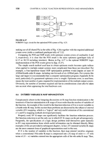
FIGURE 4.27
NOR/INV logic circuit for the optimized POS system of Fig. 4.25.
making use of all shared Pis in the table of Fig. 4.26a together with the required additional
p-term cover yields a combined gate/input tally of 7/22.
Comparing the POS and SOP results with optimum system covers of cardinality 4 and
5, respectively, it is clear that the POS result is the more optimum (gate/input tally of
6/15 or 10/19 including inverters). Shown in Fig. 4.27 is the optimal NOR/INV logic
implementation of the POS results given by Eqs. (4.37).
The simple search method used here to obtain optimum results becomes quite tedious
when applied to multiple output systems more complicated than those just described. For
example, a four-input/four-output SOP optimization problem would require at least 10
ANDed fourth-order K-maps, including one for each of six ANDed pairs. For systems this
large and larger it is recommended that a computer optimization program (Appendix B) be
used, particularly if a guaranteed optimum cover is sought. Optimum cover, as used here,
means the least number of gates required for implementation of the multiple output system.
Obviously, the number of inverters required and fan-in considerations must also be taken
into account when appraising the total hardware cost.
4.6 ENTERED VARIABLE K-MAP MINIMIZATION
Conspicuously absent in the foregoing discussions on K-map function minimization is the
treatment of function minimization in K-maps of lesser order than the number of variables of
the function. An example of this would be the function reduction of five or more variables in
a fourth-order K-map. In this section these problems are discussed by the subject of entered
variable (EV) mapping, which is a "logical" and very useful extension of the conventional
(1's and O's) mapping methods developed previously.
Properly used, EV K-maps can significantly facilitate the function reduction process.
But function reduction is not the only use to which EV K-maps can be put advantageously.
Frequently, the specifications of a logic design problem lend themselves quite naturally
to EV map representation from which useful information can be obtained directly. Many
examples of this are provided in subsequent chapters. In fact, EV (entered variable) K-maps
are the most common form of graphical representation used in this text.
If N is the number of variables in the function, then map entered variables originate
when a conventional Af th-order K-map is compressed into a K-map of order n < N with
terms of (N — n) variables entered into the appropriate cells of the nth-order K-map. Thus,