
Page 182 - Engineering Digital Design
P. 182
4.5 MULTIPLE OUTPUT OPTIMIZATION 153
Combinational
Logic
System
m-1
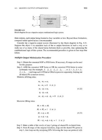
FIGURE 4.21
Block diagram for an n-input/m-output combinational logic system.
three outputs, each output being limited to four variables or less. Beyond these limitations,
computer-aided optimization is recommended.
Consider the n-input/m-output system illustrated by the block diagram in Fig. 4.21.
Suppose the object is to minimize each of the m output functions in such a way as to
make use of as many of the shared terms between them as possible, thus optimizing the
combinational logic of this system. The recommended procedure is given in four steps that
follow.
Multiple-Output Minimization Procedure
Step 1. Obtain the canonical SOP or POS forms. If necessary, K-maps can be used
for this purpose.
Step 2. AND the canonical SOP forms or OR the canonical POS forms in some
systematic way (for example, f } • f 2, / 2 • / 3, h • /4, • - •, or /i + / 2, /2 + / 3,
/3 + /4,...) and map each ANDed or ORed expression separately, looping out
all shared Pis (common terms).
Minterm ANDing rules:
nij • mi = m,
m/-m / = 0 (i ^ j )
m, • (j>j = m\ (4.32)
m/ • (f)j = fa • (j)j = 0 (i ^ j )
Maxterm ORing rules:
MI + Mi = MI
Mi + Mj = l (i^j}
Mi + 0,- = MI (4.33)
</>/ + 0, = 0/
Mi +0;=0, +0./ = 1 (i^j)
Step 3. Make a table of the results of step 2 giving all shared Pis in literal form.
Step 4. From K-maps of the original functions, loop out the shared Pis given in
step 3, then loop out the remaining EPIs following the loop-out protocol with