
Page 450 - Engineering Digital Design
P. 450
420 CHAPTER 10 / INTRODUCTION TO SYNCHRONOUS STATE MACHINE DESIGN
and climate control systems. All of these remarkable and now commonplace gifts of modern
technology are made possible through the use of digital sequential machines.
The machines just mentioned are called sequential machines, or simply state machines,
because they possess true memory and can issue time-dependent sequences of logic signals
controlled by present and past input information. These sequential machines may also be
synchronous because the data path is controlled by a system clock. In synchronous sequen-
tial machines, input data are introduced into the machine and are processed sequentially
according to some algorithm, and outputs are generated — all regulated by a system clock.
Sequential machines whose operation is clock independent (i.e., self-timed) are called asyn-
chronous sequential machines, the subject of Chapters 14, 15, and 16.
Synchronous sequential machines and their design, analysis, and operation are the sub-
jects covered in this chapter. Treatment begins with a discussion of the models used for
these machines. This is followed by a discussion of an important type of graphic that is used
to represent the sequential behavior of sequential machines and by a detailed development
of the devices used for their memory. The chapter ends with the design and analysis of rel-
atively simple state machines. The intricacies of design are numerous and require detailed
consideration. For this reason they are discussed later, in Chapter 11.
10.1.1 A Sequence of Logic States
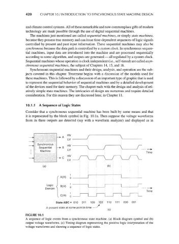
Consider that a synchronous sequential machine has been built by some means and that
it is represented by the block symbol in Fig. 10.la. Then suppose the voltage waveforms
from its three outputs are detected (say with a waveform analyzer) and displayed as in
HV
— + A
LV
Synchronous HV
Sequential -> B
Machine LV
Time
HV i .
— * C
LV ':
(a) : : : : (b)
A(H) J
Logic j B(H)
Domain ]
Time
C(H) 1
State ABC = 010 011 100 101 110 111 000 001
A present state at some point in time —'
(c)
FIGURE 10.1
A sequence of logic events from a synchronous state machine, (a) Block diagram symbol and (b)
output voltage waveforms, (c) Timing diagram representing the positive logic interpretation of the
voltage waveforms and showing a sequence of logic states.