
Page 452 - Engineering Digital Design
P. 452
422 CHAPTER 10 / INTRODUCTION TO SYNCHRONOUS STATE MACHINE DESIGN
State variables ABC _, p§ NS -^ /— State s y mbo '
(a) ^01?) ^MOcT) ^JO-T) >Alo) >Ml7) >(oOO^) >
X = Up count and X = down count
X X x x
S N
100
X ZiTif * x
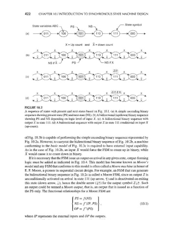
FIGURE 10.2
A sequence of states with present and next states based on Fig. 10.1. (a) A simple ascending binary
sequence showing present state (PS) and next state (NS). (b) A bidirectional (up/down) binary sequence
showing PS and NS depending on logic level of input X. (c) A bidirectional binary sequence with
output Z in state 111. (d) A bidirectional sequence with output Z in state 111 conditional on input X
(up-count).
of Fig. 10.3b is capable of performing the simple ascending binary sequence represented by
Fig. 10.2a. However, to carryout the bidirectional binary sequence of Fig. 10.2b, a machine
conforming to the foz,s7c model of Fig. 10.3c is required to have external input capability.
As in the case of Fig. 10.2b, an input X would force the FSM to count up in binary, while
X would cause it to count down in binary.
If it is necessary that the FSM issue an output on arrival in any given state, output-forming
logic must be added as indicated in Fig. 10.4. This model has become known as Moore's
model and any FSM that conforms to this model is often called a Moore machine in honor of
E. F. Moore, a pioneer in sequential circuit design. For example, an FSM that can generate
the bidirectional binary sequence in Fig. 10.2c is called a Moore FSM, since an output Z is
unconditionally activated on arrival in state 111 (up arrow, f) and is deactivated on exiting
this state (down arrow, !); hence the double arrow (|j) for the output symbol Z^f. Such
an output could be termed a Moore output, that is, an output that is issued as a function of
the PS only. The functional relationships for a Moore FSM are
PS=f(NS)
NS = f'(IP, PS) (10.1)
OP = /"(PS)
where IP represents the external inputs and OP the outputs.