
Page 456 - Engineering Digital Design
P. 456
426 CHAPTER 10 / INTRODUCTION TO SYNCHRONOUS STATE MACHINE DESIGN
(a) (b)
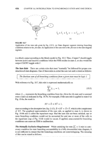
FIGURE 10.7
Application of the sum rule given by Eq. (10.3). (a) State diagram segment showing branching
conditions relative to the j th state, (b) Application of the sum rule to the j th state in the state diagram
segment.
is a Mealy output according to the Mealy model in Fig. 10.5. Thus, if input Y should toggle
between active and inactive conditions while the FSM resides in state d, so also would the
output COUNT toggle with Y.
The Sum Rule There are certain rules that must "normally" be followed for proper con-
struction of state diagrams. One of these rules is called the sum rule and is stated as follows:
The Boolean sum of all branching conditions from a given state must be logic 1.
With reference to Fig. 10.7, this rule is expressed mathematically as
n-\
^2/i^j = l, (10.3)
i=0
where /)•«_/ represents the branching condition from the yth to the /th state and is summed
over n states as indicated in Fig. 10.7b. For example, if the sum rule is applied to state b in
Fig. 10.6a, the result is
XY + X + XY = 1,
since according to the absorptive law, Eq. (3.13), X+XY = X+Y, which is the complement
of XY. The graphical representation of the sum rule, as applied to state b, is shown in
Fig. 10.6b and is called the input/state map. Had the sum rule not been satisfied, one or
more branching conditions would not be accounted for and one or more of the cells in
the input/state map of Fig. 10.6b would be vacant. If applied, unaccounted-for branching
conditions can cause an FSM to malfunction.
The Mutually Exclusive Requirement While satisfying the sum (^ = 1) rule is a nec-
essary condition for state branching accountability in a fully documented state diagram, it
is not sufficient to ensure that the branching conditions are nonoverlapping. The meaning
of this can be stated as follows: