
Page 460 - Engineering Digital Design
P. 460
430 CHAPTER 10 / INTRODUCTION TO SYNCHRONOUS STATE MACHINE DESIGN
State
a
variable Input logic
ble, Q change values
, A v r^~^
n
Q t+i s R
Reset Hold 0 -» 0 0
Set 0 -> 1 1 *
^
Reset 1 -» 0 0 1
Set Hold 1 -» 1 /1 nf
1 ^
S + R
(a) (b)
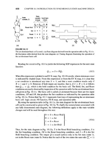
FIGURE 10.12
The set-dominant basic cell (contd.). (a) State diagram derived from the operation table in Fig. 10. lie.
(b) Excitation table derived from the state diagram, (c) Timing diagram illustrating the operation of
the set-dominant basic cell.
Reading the circuit in Fig. 10.1 la yields the following SOP expression for the next state
function:
Q t+ i=S + RQ t . (10.5)
When this expression is plotted in an EV K-map, Fig. 10.1 Ib results, where minimum cover
is indicated by shaded loops. From this expression or from the EV K-map, it is clear that
a set condition is introduced any time 5=1 , and that a reset condition results only if
R = 1 and 5 = 0. However, if both inputs are inactive, that is, if 5 = R = 0, it follows
that Qt+\ = Q t, which is the hold condition for the basic cell. The Hold, Set, and Reset
conditions are easily observed by inspection of the operation table for the set-dominant basic
cell given in Fig. 10.1 Ic. The basic cell is called set-dominant because there are two input
conditions, SR and SR, that produce the Set condition as indicated by the operation table
in Fig. 10. lie. Notice that Fig. 10.11 represents four ways of representing the set-dominant
basic cell: logic circuit, NS function, NS K-map, and operation table.
By using the operation table in Fig. 10.1 Ic, the state diagram for the set-dominant basic
cell can be constructed as given in Fig. 10.12a. To clarify the nomenclature associated with
any fully documented state diagram, the following definitions apply to the state variable
changes and will be used throughout this text:
0-> 0 = Reset Hold
0 -> l=Set
(10.6)
1^0 = Reset
1 -* 1 = Set Hold
Thus, for the state diagram in Fig. 10.12a, 5 is the Reset Hold branching condition, 5 is
the Set branching condition, SR is the Reset branching condition, and 5 + R is the Set
Hold branching condition. The output Q is issued (active) only in the Set state (state 1),
not in the Reset state (state 0). Notice that for each of the two states the sum rule (£] = 1)