
Page 462 - Engineering Digital Design
P. 462
432 CHAPTER 10 / INTRODUCTION TO SYNCHRONOUS STATE MACHINE DESIGN
State
S+R state variable Input logic
variable, Q chan e values
9
Q t-» Q t+1 S R
n
Reset Hold 0 -» 0 /O ^\ 1
R W 1/
Set 0 -> 1 1 0 R(H) i | — | I
Q1T Reset 1 -> 0 Y 1 . . .
^ 0 U(H) | j_J
Set Hold 1 -» 1
(b)
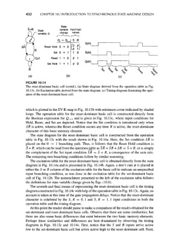
FIGURE 10.14
The reset-dominant basic cell (contd.). (a) State diagram derived from the operation table in Fig.
10.13c. (b) Excitation table derived from the state diagram, (c) Timing diagram illustrating the oper-
ation of the reset-dominant basic cell.
which is plotted in the EV K-map in Fig. 10.13b with minimum cover indicated by shaded
loops. The operation table for the reset-dominant basic cell is constructed directly from
the Boolean expression for Q t+i and is given in Fig. 10.13c, where input conditions for
Hold, Reset, and Set are depicted. Notice that the Set condition is introduced only when
SR is active, whereas the Reset condition occurs any time R is active, the reset-dominant
character of this basic memory element.
The state diagram for the reset-dominant basic cell is constructed from the operation
table in Fig. 10.13c with the result shown in Fig. 10.14a. Here, the Set condition SR is
placed on the 0 -» 1 branching path. Thus, it follows that the Reset Hold condition is
S + R, which can be read from the operationtable as SR + SR-\- SR = S + R, or is simply
the complement of the Set input condition SR = S + R, a consequence of the sum rule.
The remaining two branching conditions follow by similar reasoning.
The excitation table for the reset-dominant basic cell is obtained directly from the state
diagram in Fig. 10.14a and is presented in Fig. 10.14b. Again, a don't care 0 is placed in
either the S or R column of the excitation table for the basic cell to indicate an unspecified
input branching condition, as was done in the excitation table for the set-dominant basic
cell of Fig. 10.12b. The nomenclature presented to the left of the excitation table follows
the definitions for state variable change given by Eqs. (10.6).
The seventh and final means of representing the reset-dominant basic cell is the timing
diagram constructed in Fig. 10.14c with help of the operation table in Fig. 10.13c. Again, no
account is taken at this time of the gate propagation delays. Notice that the reset-dominant
character is exhibited by the S, R = 0, 1 and S, R = 1,1 input conditions in both the
operation table and the timing diagram.
At this point the reader should pause to make a comparison of the results obtained for the
set-dominant and reset-dominant basic cells. Observe that there are some similarities, but
there are also some basic differences that exist between the two basic memory elements.
Perhaps these similarities and differences are best dramatized by observing the timing
diagrams in Figs. 10.12c and 10.14c. First, notice that the S and R inputs arrive active
low to the set-dominant basic cell but arrive active high to the reset-dominant cell. Next,