
Page 467 - Engineering Digital Design
P. 467
10.5 INTRODUCTION TO FLIP-FLOPS 437
Rising Edge T Falling Edge
*-Time
I fl I I PI —*Time
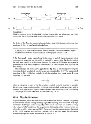
FIGURE 10.19
Clock logic waveforms, (a) Regular clock waveform showing rising and falling edges and a fixed
clock period TCK- (b) Irregular clock waveform having no fixed clock period.
the design of flip-flops, the memory elements that are used in the design synchronous state
machines. A flip-flop may be defined as follows:
A flip-flop is an asynchronous one-bit memory element (device) that exhibits sequen-
tial behavior controlled exclusively by an enabling input called CLOCK.
A flip-flop samples a data input of one bit by means of a clock signal, issues an output
response, and stores that one bit until it is replaced by another. One flip-flop is required
for each state variable in a given state diagram. For example, FSMs that are capable of
generating the 3-bit binary sequences shown in Fig. 10.2 each require three flip-flops for
their design.
The enabling input, clock, can be applied to the flip-flops as either a regular or irregular
waveform. Both types of clock waveforms are represented in Fig. 10.19. The regular clock
waveform in Fig. 10.19a is a periodic signal characterized by a clock period T CK and
frequency f CK given by
f CK=~, (10-8)
where f CK is given in units of Hz (hertz) when the clock period is specified in seconds.
The irregular clock waveform in Fig. 10.19b has no fixed clock period associated with it.
However, both regular and irregular clock waveforms must have rising (0 -» 1 ) and falling
(1 — > 0) edges associated with them, as indicated in Fig. 10.19.
10.5.1 Triggering Mechanisms
In synchronous sequential machines, state-to-state transitions occur as a result of a triggering
mechanism that is either a rising or falling edge of the enabling clock waveform. Flip-flops
and latches that trigger on the rising edge of the clock waveform are said to be rising
edge triggered (RET), and those that trigger on the falling edge of the clock waveform are
referred to as falling edge triggered (FET). These two triggering mechanisms are illustrated
in Fig. 10.20, together with the logic symbols used to represent them. The distinction
between flip-flops and latches will be made in Section 10.7.