
Page 468 - Engineering Digital Design
P. 468
438 CHAPTER 10 / INTRODUCTION TO SYNCHRONOUS STATE MACHINE DESIGN
-Active . —i Active
— > — CK I
Inactive ' '— Inactive
Flip-flop Latch Flip-flop Latch
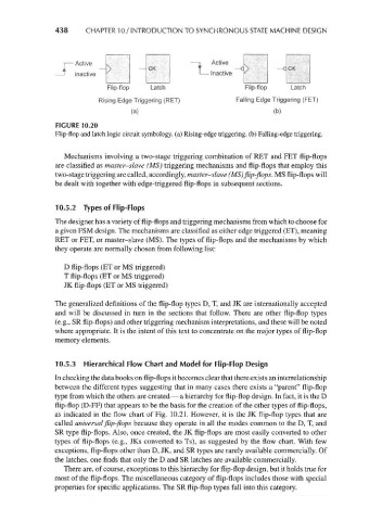
Rising Edge Triggering (RET) Falling Edge Triggering (FET)
(a) (b)
FIGURE 10.20
Flip-flop and latch logic circuit symbology. (a) Rising-edge triggering, (b) Falling-edge triggering.
Mechanisms involving a two-stage triggering combination of RET and FET flip-flops
are classified as master-slave (MS) triggering mechanisms and flip-flops that employ this
two-stage triggering are called, accordingly, master-slave (MS) flip-flops. MS flip-flops will
be dealt with together with edge-triggered flip-flops in subsequent sections.
10.5.2 Types of Flip-Flops
The designer has a variety of flip-flops and triggering mechanisms from which to choose for
a given FSM design. The mechanisms are classified as either edge triggered (ET), meaning
RET or FET, or master-slave (MS). The types of flip-flops and the mechanisms by which
they operate are normally chosen from following list:
D flip-flops (ET or MS triggered)
T flip-flops (ET or MS triggered)
JK flip-flops (ET or MS triggered)
The generalized definitions of the flip-flop types D, T, and JK are internationally accepted
and will be discussed in turn in the sections that follow. There are other flip-flop types
(e.g., SR flip-flops) and other triggering mechanism interpretations, and these will be noted
where appropriate. It is the intent of this text to concentrate on the major types of flip-flop
memory elements.
10.5.3 Hierarchical Flow Chart and Model for Flip-Flop Design
In checking the data books on flip-flops it becomes clear that there exists an interrelationship
between the different types suggesting that in many cases there exists a "parent" flip-flop
type from which the others are created — a hierarchy for flip-flop design. In fact, it is the D
flip-flop (D-FF) that appears to be the basis for the creation of the other types of flip-flops,
as indicated in the flow chart of Fig. 10.21. However, it is the JK flip-flop types that are
called universal flip-flops because they operate in all the modes common to the D, T, and
SR type flip-flops. Also, once created, the JK flip-flops are most easily converted to other
types of flip-flops (e.g., JKs converted to Ts), as suggested by the flow chart. With few
exceptions, flip-flops other than D, JK, and SR types are rarely available commercially. Of
the latches, one finds that only the D and SR latches are available commercially.
There are, of course, exceptions to this hierarchy for flip-flop design, but it holds true for
most of the flip-flops. The miscellaneous category of flip-flops includes those with special
properties for specific applications. The SR flip-flop types fall into this category.