
Page 471 - Engineering Digital Design
P. 471
10.7 THE D FLIP-FLOPS: GENERAL 441
State
variable Input logic
State change value
variable, Q
0
0 Reset
1 Set
1 Set
1 -> 0 0
u iT
Operation ^ 1 J t 1 —»• 1 1 Set Hold
Table
Excitation
(a) D Table
State (c)
Diagram
(b)
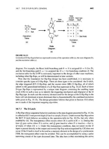
FIGURE 10.23
Generalized D flip-flop definition expressed in terms of the operation table (a), the state diagram (b),
and the excitation table (c).
diagram. For example, the Reset hold branching path 0 —> 0 is assigned D = 0 (for D),
and the Set branching path 0 —> 1 is assigned the D = 1 for branching condition D. The
excitation table for the D-FF is extremely important to the design of other state machines,
including other flip-flops, as will be demonstrated in later sections.
Now that the foundation for flip-flop design has been established, it is necessary to
consider specific types of D flip-flops. There are three types to be considered: the D-latch,
the edge triggered (ET) D flip-flop, and the master-slave (MS) D flip-flop, all of which
adhere to the generalized definition of a D flip-flop expressed in Fig. 10.23. Each of these
D-type flip-flops is represented by a unique state diagram containing the enabling input
clock (CK) in such a way as to identify the triggering mechanism and character of the D
flip-flop type. In each case the memory element used for the design of the D flip-flop is the
basic cell (set-dominant or reset-dominant) that is characterized by the combined excitation
table given in Fig. 10.15c. The design procedure follows that given in Section 10.6 where
use is made of the important mapping algorithm.
10.7.1 TheD-Latch
A flip-flop whose sequential behavior conforms to the state diagram presented in Fig. 10.24a
is called an RET transparent (high) D latch or simply D latch. Under normal flip-flop action
the RET D latch behaves according to the operation table in Fig. 10.23a, but only when
enabled by CK. The transparency effect occurs when CK is active (CK = 1). During this
time Q goes active when D is active, and Q goes inactive when D is inactive — that is,
Q tracks D when CK = 1. Under this transparency condition, data (or noise) on the D
input is passed directly to the output and normal flip-flop action (regulated by CK) does not
occur. If the D latch is itself to be used as a memory element in the design of a synchronous
FSM, the transparent effect must be avoided. This can be accomplished by using a pulse
narrowing circuit of the type discussed later. The idea here is that minimizing the active