
Page 466 - Engineering Digital Design
P. 466
436 CHAPTER 10 / INTRODUCTION TO SYNCHRONOUS STATE MACHINE DESIGN
S(L) | I
R(L)
•—
>
Q(H) -1 1
R(L)
(a) (b)
S(H)
(c) (d)
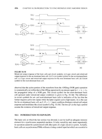
FIGURE 10.18
Mixed-rail output response of the basic cells and circuit symbols, (a) Logic circuit and mixed-rail
output response for the set-dominant basic cell, (b) Circuit symbol symbol for the set-dominant basic
cell, (c) Logic circuit and mixed-rail output response for the reset-dominant basic cell, (d) Circuit
symbol for the reset-dominant basic cell.
observed that the active portion of the waveform from the ANDing (NOR gate) operation
is symmetrically set within that of the ORing operation by an amount equal to T = r\ = T2,
the propagation delay of a NOR gate. The circuit symbol for the reset-dominant basic
cell operated under mixed-rail output conditions is given in Fig. 10.18d. The difference
in circuit symbols for set- and reset-dominant basic cells is indicative of the fact that the
former requires active low inputs while the latter requires active high inputs. As is the case
for the set-dominant basic cell, an S, R = 1, 1 input condition eliminates mixed-rail output
response and invalidates the circuit symbol in Fig. 10.18d. The two Q's in the logic symbol
assume the existence of mixed-rail output response.
10.5 INTRODUCTION TO FLIP-FLOPS
The basic cell, to which the last section was devoted, is not by itself an adequate memory
element for a synchronous sequential machine. It lacks versatility and, more importantly,
its operation cannot be synchronized with other parts of a logic circuit or system. Actually,
basic cells are asynchronous FSMs without a timing control input but which are essential to