
Page 457 - Engineering Digital Design
P. 457
10.3 THE FULLY DOCUMENTED STATE DIAGRAM 427
'n-1
f f + f +f +
n-1= O 1 2 - "
(a) (b)
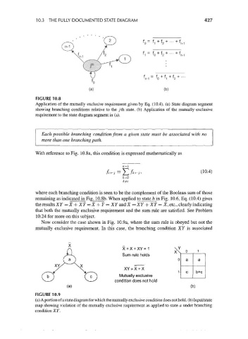
FIGURE 10.8
Application of the mutually exclusive requirement given by Eq. (10.4). (a) State diagram segment
showing branching conditions relative to the jth state, (b) Application of the mutually exclusive
requirement to the state diagram segment in (a).
Each possible branching condition from a given state must be associated with no
more than one branching path.
With reference to Fig. 10.8a, this condition is expressed mathematically as
-
/*-;. (10 4)
where each branching condition is seen to be the complement of the Boolean sum of those
remaining as indicated in Fig. 10.8b. When applied to state b in Fig. 10.6, Eq. (10.4) gives
the results XY = X + XY = X + Y = XY and X = XY + XY = X, etc., clearly indicating
that both the mutually exclusive requirement and the sum rule are satisfied. See Problem
10.24 for more on this subject.
Now consider the case shown in Fig. 10.9a, where the sum rule is obeyed but not the
mutually exclusive requirement. In this case, the branching condition XY is associated
X + X + XY = 1
Sum rule holds
XY * X + X
Mutually exclusive
condition does not hold
(b)
FIGURE 10.9
(a) A portion of a state diagram for which the mutually exclusive condition does not hold, (b) Input/state
map showing violation of the mutually exclusive requirement as applied to state a under branching
condition XY.