
Page 455 - Engineering Digital Design
P. 455
10.3 THE FULLY DOCUMENTED STATE DIAGRAM 425
Present state or NS if XY -» XY
(PS)
State code assignment
NS ifXY->XY
Conditional
r output
COUNT IT ifY
Unconditional Branching
out ut
P paths
(a) (b)
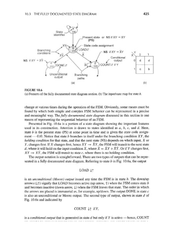
FIGURE 10.6
(a) Features of the fully documented state diagram section, (b) The input/state map for state b.
change at various times during the operation of the FSM. Obviously, some means must be
found by which both simple and complex FSM behavior can be represented in a precise
and meaningful way. The fully documented state diagram discussed in this section is one
means of representing the sequential behavior of an FSM.
Presented in Fig. 10.6a is a portion of a state diagram showing the important features
used in its construction. Attention is drawn to states identified as a, b, c, and d. Here,
state b is the present state (PS) at some point in time and is given the state code assign-
ment • • • 010. Notice that state b branches to itself under the branching condition XY, the
holding condition for that state, and that the next state (NS) depends on which input, X or
Y, changes first. If X changes first, hence XY —>• XY, the FSM will transit to the next state
d, where it will hold on the input condition X, where X = XY + XY. Or if F changes first,
XY -> XY, the FSM will transit to state c, where there is no holding condition.
The output notation is straightforward. There are two types of outputs that can be repre-
sented in a fully documented state diagram. Referring to state b in Fig. 10.6a, the output
LOAD |t
is an unconditional (Moore) output issued any time the FSM is in state b. The down/up
arrows (It) signify that LOAD becomes active (up arrow, y) when the FSM enters state b
and becomes inactive (down arrow, |) when the FSM leaves that state. The order in which
the arrows are placed is immaterial as, for example, up/down. The output DONE in state c
is also an unconditional or Moore output. The second type of output, shown in state d of
Fig. 10.6a and indicated by
COUNT If if r,
is a conditional output that is generated in state d but only if Y is active — hence, COUNT