
Page 454 - Engineering Digital Design
P. 454
424 CHAPTER 10 / INTRODUCTION TO SYNCHRONOUS STATE MACHINE DESIGN
*
External Output Outputs
Next State Forming
(IP) Forming •as* F s , Logic (OP)
' Memory
Logic
-*•
PS Feedback
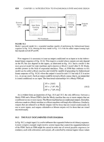
FIGURE 10.5
Mealy's (general) model for a sequential machine capable of performing the bidirectional binary
sequence in Fig. 10.2d, showing the basic model in Fig. 10.3c with the added output-forming logic
that depends on both IP and PS.
Now suppose it is necessary to issue an output conditional on an input as in the bidirec-
tional binary sequence of Fig. 10.2d. This requires a model whose outputs not only depend
on the PS, but also depend on the inputs, as illustrated in Fig. 10.5. Such a model is the
most general model for state machines and is known as Mealy's model after G. H. Mealy,
another pioneer in the field of sequential machines. Thus, an FSM that conforms to this
model can be called a Mealy machine and would be capable of generating the bidirectional
binary sequence of Fig. 10.2d, where the output is issued in state 111 but only if X is active
(i.e., on an up count). Such an output could be termed a Mealy output, that is, an output that
is issued conditional on an input. The functional relationships for a Mealy FSM are
PS = f(NS)
NS = f'(IP, PS) (10.2)
OP = f"(IP, PS)
As is evident from an inspection of Figs. 10.4 and 10.5, the only difference between a
Mealy FSM and a Moore FSM is that the Mealy machine has one or more outputs that are
conditional on one or more inputs. The Moore machine has no conditional outputs. Hereafter,
reference made to a Mealy machine or a Moore machine will imply this difference. Similarly,
outputs that are referred to as Mealy outputs will be those that are issued conditionally on
one or more inputs, and outputs referred to as Moore outputs will be those that are issued
unconditionally.
10.3 THE FULLY DOCUMENTED STATE DIAGRAM
In Fig. 10.2, a single input X is used to influence the sequential behavior of a binary sequence.
A more complex example might involve several inputs that control the sequential behavior
of the FSM. Such an FSM might be caused to enter one of several possible sequences (or
routines), each with subroutines and outputs, all controlled by external inputs whose values