Page 438 - Engineering Electromagnetics, 8th Edition
P. 438
420                ENGINEERING ELECTROMAGNETICS

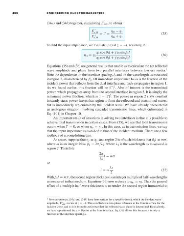
                                     (34a) and (34b) together, eliminating E xs2 ,to obtain

                                                              E  −       η in − η 1                  (35)
                                                               x10
                                                              E  +  =   =  η in + η 1
                                                               x10
                                     To find the input impedance, we evaluate (32) at z =−l, resulting in

                                                                η 3 cos β 2 l + jη 2 sin β 2 l
                                                         η in = η 2                                  (36)
                                                                η 2 cos β 2 l + jη 3 sin β 2 l

                                     Equations (35) and (36) are general results that enable us to calculate the net reflected
                                     wave amplitude and phase from two parallel interfaces between lossless media. 1
                                     Note the dependence on the interface spacing, l, and on the wavelength as measured
                                     in region 2, characterized by β 2 .Of immediate importance to us is the fraction of the
                                     incident power that reflects from the dual interface and back-propagates in region 1.
                                                                          2
                                     As we found earlier, this fraction will be | | . Also of interest is the transmitted
                                     power, which propagates away from the second interface in region 3. It is simply the
                                                                        2
                                     remaining power fraction, which is 1 −| | . The power in region 2 stays constant
                                     in steady state; power leaves that region to form the reflected and transmitted waves,
                                     butis immediately replenished by the incident wave. We have already encountered
                                     an analogous situation involving cascaded transmission lines, which culminated in
                                     Eq. (101) in Chapter 10.
                                        An important result of situations involving two interfaces is that it is possible to
                                     achieve total transmission in certain cases. From (35), we see that total transmission
                                     occurs when   = 0, or when η in = η 1 .In this case, as in transmission lines, we say
                                     that the input impedance is matched to that of the incident medium. There are a few
                                     methods of accomplishing this.
                                        As a start, suppose that η 3 = η 1 , and region 2 is of such thickness that β 2 l = mπ,
                                     where m is an integer. Now β 2 = 2π/λ 2 , where λ 2 is the wavelength as measured in
                                     region 2. Therefore
                                                                  2π
                                                                     l = mπ
                                                                  λ 2
                                     or

                                                                   l = m  λ 2                        (37)
                                                                        2
                                     Withβ 2 l = mπ,thesecondregionthicknessisanintegermultipleofhalf-wavelengths
                                     as measured in that medium. Equation (36) now reduces to η in = η 3 . Thus the general
                                     effect of a multiple half-wave thickness is to render the second region immaterial to


                                     1  For convenience, (34a) and (34b)have been written for a specific time at which the incident wave
                                     amplitude, E x10 , occurs at z =−l. This establishes a zero-phase reference at the front interface for the
                                             +
                                     incident wave, and so it is from this reference that the reflected wave phase is determined. Equivalently,
                                     we have repositioned the z = 0 point at the front interface. Eq. (36) allows this because it is only a
                                     function of the interface spacing, l.

