
Page 433 - Engineering Electromagnetics, 8th Edition
P. 433
CHAPTER 12 Plane Wave Reflection and Dispersion 415
Further insights can be obtained by working with Eq. (19) and rewriting it in real
instantaneous form. The steps are identical to those taken in Chapter 10, Eqs. (81)
through (84). We find the total field in region 1 to be
E x1T (z, t) = (1 −| |)E + cos(ωt − β 1 z)
x10
traveling wave
+ 2| |E + cos(β 1 z + φ/2) cos(ωt + φ/2) (26)
x10
standing wave
The field expressed in Eq. (26) is the sum of a traveling wave of amplitude
(1 −| |)E + and a standing wave having amplitude 2| |E x10 . The portion of the in-
+
x10
cident wave that reflects and back-propagates in region 1 interferes with an equivalent
portion of the incident wave to form a standing wave. The rest of the incident wave
(that does not interfere) is the traveling wave part of (26). The maximum amplitude
observed in region 1 is found where the amplitudes of the two terms in (26) add
directly to give (1 +| |)E + . The minimum amplitude is found where the standing
x10
wave achieves a null, leaving only the traveling wave amplitude of (1−| |)E + . The
x10
fact that the two terms in (26) combine in this way with the proper phasing can be
confirmed by substituting z max and z min ,asgiven by (22) and (25).
EXAMPLE 12.2
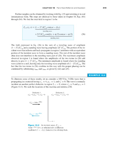
To illustrate some of these results, let us consider a 100-V/m, 3-GHz wave that is
propagating in a material having r1 = 4, µ r1 = 1, and = 0. The wave is normally
r
incident on another perfect dielectric in region 2, z > 0, where r2 = 9 and µ r2 = 1
(Figure 12.3). We seek the locations of the maxima and minima of E.
Figure 12.3 An incident wave, E xs1 =
+
100e − j 40πz V/m, is reflected with a reflection
coefficient =−0.2. Dielectric 2 is infinitely thick.