Page 431 - Engineering Electromagnetics, 8th Edition
P. 431
CHAPTER 12   Plane Wave Reflection and Dispersion      413

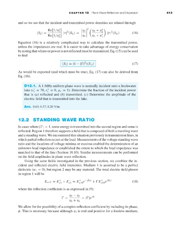
                     and so we see that the incident and transmitted power densities are related through
                                                            2

                                      Re 1/η ∗ 2          η 1     η 2 + η ∗
                                                                         2
                                                2
                                S 2  =         |τ|  S 1i  =         2  |τ|  S 1i     (16)
                                      Re 1/η ∗ 1           η 2     η 1 + η ∗ 1
                     Equation (16) is a relatively complicated way to calculate the transmitted power,
                     unless the impedances are real. It is easier to take advantage of energy conservation
                     bynotingthatwhateverpowerisnotreflectedmustbetransmitted.Eq.(15)canbeused
                     to find
                                                          2                          (17)
                                               S 2  = (1 −| | ) S 1i
                     As would be expected (and which must be true), Eq. (17) can also be derived from
                     Eq. (16).

                        D12.1. A 1-MHz uniform plane wave is normally incident onto a freshwater
                        lake (  = 78,   = 0, µ r = 1). Determine the fraction of the incident power


                                     r
                              r
                        that is (a) reflected and (b) transmitted. (c) Determine the amplitude of the
                        electric field that is transmitted into the lake.
                        Ans. 0.63; 0.37; 0.20 V/m


                     12.2 STANDING WAVE RATIO
                     In cases where | | < 1, some energy is transmitted into the second region and some is
                     reflected. Region 1 therefore supports a field that is composed of both a traveling wave
                     and a standing wave. We encountered this situation previously in transmission lines, in
                     which partial reflection occurs at the load. Measurements of the voltage standing wave
                     ratio and the locations of voltage minima or maxima enabled the determination of an
                     unknown load impedance or established the extent to which the load impedance was
                     matched to that of the line (Section 10.10). Similar measurements can be performed
                     on the field amplitudes in plane wave reflection.
                         Using the same fields investigated in the previous section, we combine the in-
                     cident and reflected electric field intensities. Medium 1 is assumed to be a perfect
                     dielectric (α 1 = 0), but region 2 may be any material. The total electric field phasor
                     in region 1 will be
                                    E x1T = E  +  + E  −  = E x10 e − jβ 1 z  +  E  +  e  jβ 1 z  (18)
                                                       +
                                                 x1
                                            x1
                                                                   x10
                     where the reflection coefficient is as expressed in (9):
                                                  η 2 − η 1   jφ
                                               =        =| |e
                                                  η 2 + η 1
                     We allow for the possibility of a complex reflection coefficient by including its phase,
                     φ. This is necessary because although η 1 is real and positive for a lossless medium,

