
Page 436 - Engineering Electromagnetics, 8th Edition
P. 436
418 ENGINEERING ELECTROMAGNETICS
in
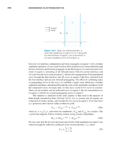
Figure 12.4 Basic two-interface problem, in
which the impedances of regions 2 and 3, along with
the finite thickness of region 2, are accounted for in
the input impedance at the front surface, η in .
from the two-interface configuration and back-propagates in region 1 with a definite
amplitude and phase; (2) an overall fraction of the incident wave is transmitted through
the two interfaces and forward-propagates in the third region; (3) a net backward wave
exists in region 2, consisting of all reflected waves from the second interface; and
(4) a net forward wave exists in region 2, which is the superposition of the transmitted
wave through the first interface and all waves in region 2 that have reflected from
the first interface and are now forward-propagating. The effect of combining many
co-propagating waves in this way is to establish a single wave which has a definite
amplitude and phase, determined through the sums of the amplitudes and phases of all
the component waves. In steady state, we thus have a total of five waves to consider.
These are the incident and net reflected waves in region 1, the net transmitted wave
in region 3, and the two counterpropagating waves in region 2.
The situation is analyzed in the same manner as that used in the analysis of
finite-length transmission lines (Section 10.11). Let us assume that all regions are
composed of lossless media, and consider the two waves in region 2. If we take these
as x-polarized, their electric fields combine to yield
E xs2 = E + e − jβ 2 z + E − e jβ 2 z (28a)
x20
x20
√
where β 2 = ω r2 /c, and where the amplitudes, E + and E − , are complex. The
x20
x20
y-polarized magnetic field is similarly written, using complex amplitudes:
H ys2 = H + e − jβ 2 z + H y20 e jβ 2 z (28b)
−
y20
We now note that the forward and backward electric field amplitudes in region 2 are
related through the reflection coefficient at the second interface, 23 , where
η 3 − η 2
23 = (29)
η 3 + η 2