
Page 31 - Subyek Computer Aided Design - [David Planchard] Engineering Design with SOLIDWORKS
P. 31
Engineering Design with SOLIDWORKS® 2018 Introduction
About the Book
You will find a wealth of information in this book. The following conventions are used
throughout the text:
• The term document is used to refer to a SOLIDWORKS part, drawing or assembly
file.
• The list of items across the top of the SOLIDWORKS interface is the Main menu.
Each item in the Main menu has a pull-down menu. When you need to select a series
of commands from these menus, the following format is used: Click Insert,
Reference Geometry, Plane from the Main bar. The Plane PropertyManager is
displayed.
• Screen shots in the book were made using SOLIDWORKS 2018 SPO running
Windows® 10.
• The ANSI overall drafting standard and Third Angle projection is used as the default
setting in this text. IPS (inch, pound, second) and MMGS (millimeter, gram, second)
unit systems are used.
• Redeem your code on the inside cover of the book. View the provided videos and
models to enhance the user experience. All templates, logos and model documents
along with additional support materials are available.
, 1 /
~Q, The book is designed to expose the new SOLIDWORKS user to many tools,
techniques and procedures. It may not always use the most direct tool or process. Learn
by doing, not just by reading.
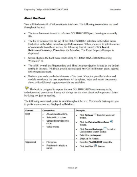
The following command syntax is used throughout the text. Commands that require you
to perform an action are displayed in Bold text.
Format: Convention: Examole:
Bold • All commands actions . • Click Options @ from the Menu bar
• Selected icon button. toolbar .
• Selected geometry: line, Click the Extruded Boss/Base ~
circle. •
feature.
• Value entries .
• Click Comer Rectangle Cl from the
Consolidated Sketch toolbar.
• Select the centerpoint .
• Enter 3.0 for Radius .
Capitalized • Filenames. • Save the FLASHLIGHT assembly.
• First letter in a feature • Click the Fillet l:B feature.
name.
PAGE I - 27