
Page 30 - Subyek Computer Aided Design - [David Planchard] Engineering Design with SOLIDWORKS
P. 30
Introduction Engineering Design with SOLIDWORKS® 2018
¢ 4
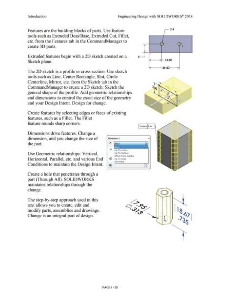
Features are the building blocks of parts. Use feature
tools such as Extruded Boss/Base, Extruded Cut, Fillet,
etc. from the Features tab in the CommandManager to )_
.-
- .
,: -
create 3 D parts. - 1 - 1
Extruded features begin with a 2D sketch created on a 1 1
Sketch plane. 16.50
39.50
The 2D sketch is a profile or cross section. Use sketch
tools such as Line, Center Rectangle, Slot, Circle
Centerline, Mirror, etc. from the Sketch tab in the
CommandManager to create a 2D sketch. Sketch the
general shape of the profile. Add geometric relationships
and dimensions to control the exact size of the geometry
and your Design Intent. Design for change.
Create features by selecting edges or faces of existing
features, such as a Fillet. The Fillet
feature rounds sharp comers.
Radius: O.Sin
Dimensions drive features. Change a
dimension, and you change the size of Direction 1
111
the part. ~ Blind
.l4 Up To Vertex =·
Use Geometric relationships: Vertical, Up To Surface
Offset From Surface
Horizontal, Parallel, etc. and various End ~ Up To Body II
Mid Plane
Conditions to maintain the Design Intent.
I
........_,....
Create a hole that penetrates through a
part (Through All). SOLIDWORKS
maintains relationships through the
change.
The step-by-step approach used in this
text allows you to create, edit and
modify parts, assemblies and drawings.
Change is an integral part of design.
l ,
PAGE I - 26