
Page 343 - Subyek Computer Aided Design - [David Planchard] Engineering Design with SOLIDWORKS
P. 343
Engineering Design with SOLIDWORKS® 2018 Fundamentals of Drawing
Fit the drawing to the Graphics window.
408) Press the f key.
409) Drag the views and annotations if required for spacing.
Save the GUIDE drawing.
410) Click Save Ii.
, 1 /
-;Q~ Establish Custom Properties early in the design process. The MATERIAL and
FINISH Custom Properties are established in the part and propagate to the Title block in
the drawing.
, 1 /
-;Q~ Create engineering procedures to define the location and values of Custom
Properties. The REVISION Custom Property was created in the drawing in the
REVISION Table. The REVISION Custom Property can also be established in the part
and propagate to the drawing. Does the part or the drawing control the revision? Your
company's engineering procedures determine the answer.
Additional annotations are required for drawings. Utilize the Surface Finish ~ tool to
apply symbols to individual faces/edges in the part or in the drawing. When an assembly
contains mating parts, document their relationship. Add part numbers in the Used On
section. Additional annotations are left as an exercise.
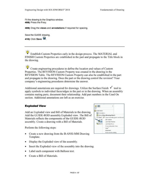
Exploded View ~ IEI >
'v
I~~ GUIDE-ROD
Add an Exploded view and Bill of Materials to the drawing. IA] Annotations
Add the GUIDE-ROD assembly Exploded view. The Bill of ~ eDrawi1 View (Drawing View1 )
• D Sheet1 ~ Open Assembly (guide-rod.sldasm)
Materials reflects the components of the GUIDE-ROD
Edit Feature
assembly. Create a drawing with a Bill of Materials. Ora Lock View Position
"""""""'-
~ Bill of ti Lock View Focus
Sho~n Exploded State
Perform the following steps: Hide
Alignment
Reset sketch visi bi I ity
• Create a new drawing from the B-ANSI-MM Drawing
Template.
• Display the Exploded view of the assembly.
• Insert the Exploded view of the assembly into the drawing.
• Label each component with Balloon text.
• Create a Bill of Materials.
PAGE4 - 67