
Page 338 - Subyek Computer Aided Design - [David Planchard] Engineering Design with SOLIDWORKS
P. 338
Fundamentals of Drawing Engineering Design with SOLIDWORKS® 2018
Utilize the following prefix codes to categories, created parts and drawings. The part
name, part number and drawing numbers are as follows:
Cateaorv: Prefix: Part Name: Part Number: Drawina Number:
Machined Parts 56- GUIDE 56-A26 56-22222
ROD 56-A27 56-22223
PLATE 56-A28 56-22224
Purchased Parts 99- FLANGE BOLT 99-FBM8x1 .25 999-551-8
Assemblies 10- GUIDE-ROD 10-A123 10-50123
Link notes in the Title block to SOLIDWORKS Properties. The title of the drawing is
linked to the GUIDE Part Description, GUIDE-SUPPORT. Create additional notes in the
Title block that complete the drawing.
Additional notes are required in the Title block. The text box headings SIZE B, DWG.
NO., REV., SCALE, WEIGHT and SHEET OF are entered in the SOLIDWORKS
default Sheet Format. Properties are variables shared between documents and
applications. Define the Document Properties in the GUIDE drawing. Link the Document
Properties to the notes in the Title block.
Activity: Part Number and Document Properties
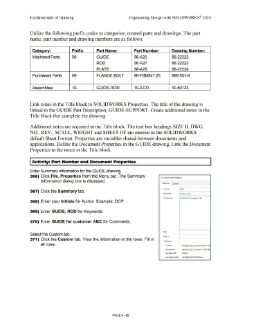
Enter Summary information for the GUIDE drawing.
366) Click File, Properties from the Menu bar. The Summary Summary Information
Information dialog box is displayed.
Summary Custom
Author: DCP
367) Click the Summary tab.
Kevwords: GUIDE, ROD
Comments: GUIDE FOR customer ABC
368) Enter your initials for Author. Example: DCP.
369) Enter GUIDE, ROD for Keywords.
370) Enter GUIDE for customer ABC for Comments.
Title:
Select the Custom tab.
Subj ect:
371) Click the Custom tab. View the information in the rows. Fill in
Statistics
all rows. Created: Monday, July 24, 2017 9:04:17 AM
Last Saved: Monday, July 24, 2017 1 :26:45 PM
Last Saved By: Dave pl
Last Saved With: SOLIDWORKS 2018 Beta1
PAGE4 -62