
Page 374 - Subyek Computer Aided Design - [David Planchard] Engineering Design with SOLIDWORKS
P. 374
Extrude and Revolve Features Engineering Design with SOLIDWORKS® 2018
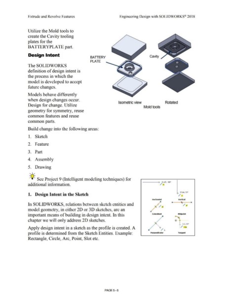
Utilize the Mold tools to
create the Cavity tooling
plates for the
BATTERYPLATE part.
Design Intent
BATIERY Cavity
PLATE
The SOLIDWORKS
definition of design intent is
the process in which the
model is developed to accept
future changes.
Models behave differently
when design changes occur.
Isometric view Rotated
Design for change. Utilize
Mold tools
geometry for symmetry, reuse
common features and reuse
common parts.
Build change into the following areas:
1. Sketch
2. Feature
3. Part
4. Assembly
5. Drawing
, ,/
-;Q;_ See Project 9 (Intelligent modeling techniques) for
---::- 30.58, 180°
additional information. / -
, 19 .04, 900
1. Design Intent in the Sketch -,-/ I
Horizontal Vertical
,/ a ~ CJ
In SOLIDWORKS, relations between sketch entities and -,- / J"1
/ j(.
model geometry, in either 2D or 3D sketches, are an
important means of building in design intent. In this Coincident Midpoint
chapter we will only address 2D sketches.
_ _ 0.3, 90•
'
Apply design intent in a sketch as the profile is created. A : / 10\
/ .L
profile is determined from the Sketch Entities. Example: Perpendicular Tangent
Rectangle, Circle, Arc, Point, Slot etc.
PAGE 5 - 6