
Page 376 - Subyek Computer Aided Design - [David Planchard] Engineering Design with SOLIDWORKS
P. 376
Extrude and Revolve Features Engineering Design with SOLIDWORKS® 2018
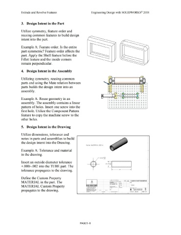
3. Design Intent in the Part
Utilize symmetry, feature order and
reusing common features to build design
intent into the part.
Example A: Feature order. Is the entire
part symmetric? Feature order affects the
part. Apply the Shell feature before the
Fillet feature and the inside comers
remain perpendicular.
4. Design Intent in the Assembly
Utilizing symmetry, reusing common
parts and using the Mate relation between
parts builds the design intent into an 000000000000@ 0
000000000000@ 0
assembly. 000000000000@ 0
Example A: Reuse geometry in an 0 0 0
0 0 0 0 0 0 0 0 0 0 0 0 0 0 0 0 0
assembly. The assembly contains a linear 0 0 0 0 0 0 0 0 0 0 0 0 0 0 0 0 0
0 0 0 0 0 0 0 0 0 0 0 0 0 0 0 0 0
pattern of holes. Insert one screw into the 0 0 0 0 0 0 0 0 0 0 0 0 0 0 0 0 0
first hole. Utilize the Component Pattern
feature to copy the machine screw to the
other holes.
5. Design Intent in the Drawing
Utilize dimensions, tolerance and
notes in parts and assemblies to build
the design intent into the Drawing.
Note : MATERIAL SS3l 6
Example A: Tolerance and material c
in the drawing.
<I> lSO +.00•
· .000 ..
Insert an outside diameter tolerance ' ---------------------------------------
it>.162~ : ~
+.000/-.002 into the TUBE part. The l__ ...................................... . •
~- .600 -----i
tolerance propagates to the drawing.
Define the Custom Property
MATERIAL in the part. The ..
MATERIAL Custom Property TUBE
propagates to the drawing.
PAGE 5 - 8